Of greatest practical interest is the magnetic field of a current-carrying coil. Figure 97 shows a coil consisting of a large number turns of wire wound on a wooden frame. When there is current in the coil, the iron filings are attracted to its ends; when the current is turned off, they fall off.
Rice. 97. Attraction of iron filings by a coil with current
If a coil with current is suspended on thin and flexible conductors, then it will be installed in the same way as the magnetic needle of a compass. One end of the coil will face north, the other will face south. This means that a coil with current, like a magnetic needle, has two poles - north and south (Fig. 98).

Rice. 98. Poles of the coil with current
There is a magnetic field around a current carrying coil. It, like the direct current field, can be detected using sawdust (Fig. 99). The magnetic lines of the magnetic field of a coil with current are also closed curves. It is generally accepted that outside the coil they are directed from north pole coils to the south (see Fig. 99).

Rice. 99. Magnetic lines of the coil with current
Coils with current are widely used in technology as magnets. They are convenient in that they magnetic action can be changed (strengthened or weakened) over a wide range. Let's take a look at the ways in which we can do this.
Figure 97 shows an experiment in which the action of the magnetic field of a coil with current is observed. If you replace the coil with another one with a larger number of turns of wire, then with the same current strength, it will attract more iron objects. Means, the magnetic effect of a coil with current is stronger than more number coils in it.
We will include a rheostat in the circuit containing the coil (Fig. 100) and with the help of it we will change the current strength in the coil. With an increase in the current strength, the effect of the magnetic field of the coil with current increases, with a decrease, it weakens.

Rice. 100. The action of the magnetic field of the coil
It also turns out that the magnetic effect of a coil with current can be significantly increased without changing the number of its turns and the current strength in it. To do this, you need to insert an iron rod (core) inside the coil. Iron inserted inside the coil enhances the magnetic effect of the coil.(Fig. 101).

Rice. 101. The action of the magnetic field of a coil with an iron core
A coil with an iron core inside is called an electromagnet.
An electromagnet is one of the main parts of many technical devices. Figure 102 shows an arc-shaped electromagnet holding an anchor (an iron plate) with a suspended load.

Rice. 102. Arcuate electromagnet
Electromagnets are widely used in engineering due to their remarkable properties. They quickly demagnetize when the current is turned off, depending on the purpose they can be made in a variety of sizes, while the electromagnet is operating, its magnetic effect can be adjusted by changing the current strength in the coil.
Electromagnets with a large lifting force are used in factories to carry products made of steel or cast iron, as well as steel and cast iron shavings, ingots (Fig. 103).

Rice. 103. Application of electromagnets
Figure 104 shows a sectional view of a magnetic grain separator. Very fine iron filings are mixed into the grain. These sawdust do not stick to smooth grains of useful cereals, but stick to weed grains. Grains 1 are poured out of the hopper onto a rotating drum 2. Inside the drum there is a strong electromagnet 5. By attracting iron particles 4, it removes weed grains from the grain flow 3 and in this way cleans the grain from weeds and accidentally fallen iron objects.

Rice. 104. Magnetic separator
Electromagnets are used in telegraph, telephone sets and in many other devices.
Questions
- In what direction is a current-carrying coil suspended on long thin conductors mounted? What similarity does it have with a magnetic needle?
- What are some ways to increase the magnetic effect of a current-carrying coil?
- What is an electromagnet?
- What is the purpose of electromagnets in factories?
- How does a magnetic grain separator work?
Exercise 41
- It is necessary to build an electromagnet, the lifting force of which can be adjusted without changing the design. How to do it?
- What needs to be done to change magnetic poles coils with current in opposite directions?
- How to build a strong electromagnet if the designer is given the condition that the current in the electromagnet is relatively small?
- The electromagnets used in the crane have enormous power. Electromagnets, with the help of which iron filings accidentally get out of the eyes, are very weak. How is this difference achieved?
Exercise

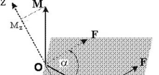
A conductor through which an electric current flows creates a magnetic field which is characterized by the intensity vector `H(Fig. 3). The magnetic field strength obeys the superposition principle
and, according to the Biot-Savart-Laplace law,
where I is the current strength in the conductor, is a vector having the length of an elementary segment of the conductor and directed in the direction of the current, `r is the radius vector connecting the element with the considered point P.
 One of the most common configurations of conductors with current is a coil in the form of a ring of radius R (Fig. 3, a). The magnetic field of such a current in the plane passing through the axis of symmetry has the form (see Fig. 3, b). The field as a whole must have rotational symmetry about the z axis (Fig. 3, b), and the lines of force themselves must be symmetrical about the loop plane (the plane xy). The field in the immediate vicinity of the conductor will resemble the field near a long straight wire, since the influence of the remote parts of the loop is relatively small here. On the axis of the circular current, the field is directed along the axis Z.
Let us calculate the magnetic field strength on the axis of the ring at a point located at a distance z from the plane of the ring. According to formula (6), it suffices to calculate the z-component of the vector :
![]() . (7)
. (7)
Integrating over the entire ring, we obtain òd l= 2p R. Since, according to the Pythagorean theorem r 2 = R 2 + z 2 , then the required field at a point on the axis is
![]() . (8)
. (8)
vector direction `H can be directed according to the rule of the right screw.
In the center of the ring z= 0 and formula (8) is simplified:
We are interested in short coil- a cylindrical wire coil, consisting of N turns of the same radius. Due to axial symmetry and in accordance with the principle of superposition, the magnetic field of such a coil on the H axis is the algebraic sum of the fields of individual turns H i: . Thus, the magnetic field of a short coil containing N to turns, at an arbitrary point on the axis is calculated by the formulas
![]() ,
, ![]() , (10)
, (10)
where H- tension, B– magnetic field induction.
Magnetic field of a solenoid with current
To calculate the magnetic field induction in the solenoid, the theorem on the circulation of the magnetic induction vector is used:
![]() , (11)
, (11)
where - algebraic sum currents covered by the circuit L freeform, n- the number of conductors with currents covered by the circuit. In this case, each current is taken into account as many times as it is covered by the circuit, and the current is considered positive, the direction of which forms a right-hand screw system with the direction of bypass along the circuit - the circuit element L.
Let us apply the theorem on the circulation of the magnetic induction vector to a solenoid of length l having N with turns with current I(Fig. 4). In the calculation, we take into account that almost the entire field is concentrated inside the solenoid (edge effects are neglected) and it is homogeneous. Then formula 11 will take the form:
![]() ,
,
from where we find the magnetic field induction created by the current inside the solenoid:
 |
Rice. 4. Solenoid with current and its magnetic field
 Installation scheme
Rice. 5 Schematic diagram of the installation
1 - magnetic field induction meter (teslameter), A - ammeter, 2 - connecting wire, 3 - measuring probe, 4 - Hall sensor *, 5 - object under study (short coil, straight conductor, solenoid), 6 - current source, 7 - a ruler for fixing the position of the sensor, 8 - probe holder.
* - the principle of operation of the sensor is based on the phenomenon of the Hall effect (see lab. work No. 15 Study of the Hall effect)
Work order
1. Study of the magnetic field of a short coil
1.1. Turn on appliances. The power supply and teslameter switches are located on the rear panels.
1.2. As an object under study 5 (see Fig. 5), place a short coil in the holder and connect it to the current source 6.
 1.3. Set the voltage regulator on the source 6 to the middle position. Set the current strength to zero by adjusting the current strength output at source 6 and control it with an ammeter (the value must be zero).
1.4. Coarse 1 and fine tuning 2 regulators (Fig. 6) achieve zero readings of the teslameter.
1.5. Install the holder with the measuring probe on the ruler in a position convenient for reading - for example, at the 300 mm coordinate. In the future, take this position as zero. During installation and during measurements, observe the parallelism between the probe and the ruler.
 1.6. Position the holder with the short coil in such a way that the Hall sensor 4 is in the center of the coil turns (Fig. 7). To do this, use the clamping and height adjustment screw on the probe holder. The plane of the coil must be perpendicular to the probe. In the process of preparing measurements, move the holder with the test sample, leaving the measuring probe motionless.
1.7. Make sure that during the warm-up time of the teslameter, its readings remain zero. If this is not done, set the teslameter to zero at zero current in the sample.
1.8. Set the short coil current to 5 A (by adjusting the output on power supply 6, Constanter/Netzgerät Universal).
1.9. Measure magnetic induction B exp on the axis of the coil depending on the distance to the center of the coil. To do this, move the probe holder along the ruler, keeping parallel to its original position. Negative values z correspond to the probe displacement to the region of smaller coordinates than the initial one, and vice versa - positive values of z - in the region of large coordinates. Enter the data in table 1.
Table 1 Dependence of the magnetic induction on the axis of a short coil on the distance to the center of the coil
1.10. Repeat points 1.2 - 1.7.
1.11. Measure the dependence of the induction at the center of the coil on the strength of the current passing through the coil. Enter the data in table 2.
Table 2 Dependence of the magnetic induction in the center of a short coil on the current strength in it
 2. Study of the magnetic field of the solenoid
2.1. As an object under study 5, place the solenoid on a metal bench of non-magnetic material adjustable in height (Fig. 8).
2.2. Repeat 1.3 - 1.5.
2.3. Adjust the height of the bench so that the measuring probe passes along the axis of symmetry of the solenoid, and the Hall sensor is in the middle of the turns of the solenoid.
2.4. Repeat steps 1.7 - 1.11 (a solenoid is used instead of a short coil). Enter the data in tables 3 and 4, respectively. In this case, determine the coordinate of the solenoid center as follows: install the Hall sensor at the beginning of the solenoid and fix the coordinate of the holder. Then move the holder along the ruler along the axis of the solenoid until the end of the sensor is on the other side of the solenoid. Fix the coordinate of the holder in this position. The solenoid center coordinate will be equal to the arithmetic mean of the two measured coordinates.
Table 3 Dependence of the magnetic induction on the solenoid axis on the distance to its center.
2.5. Repeat points 1.3 - 1.7.
2.6. Measure the dependence of the induction at the center of the solenoid on the strength of the current passing through the coil. Enter the data in table 4.
Table 4 Dependence of the magnetic induction in the center of the solenoid on the current strength in it
3. Study of the magnetic field of a direct conductor with current
 3.1. As the object under study 5, install a straight conductor with current (Fig. 9, a). To do this, connect the wires coming from the ammeter and the power source to each other (short the external circuit) and place the conductor directly on the edge of probe 3 near sensor 4, perpendicular to the probe (Fig. 9, b). To support the conductor, use a height-adjustable metal bench made of non-magnetic material on one side of the probe and a holder for test samples on the other side (one of the holder sockets can include a conductor terminal for more reliable fixation of this conductor). Give the conductor a straight shape.
3.2. Repeat points 1.3 - 1.5.
3.3. Determine the dependence of magnetic induction on the current strength in the conductor. Enter the measured data in table 5.
Table 5 Dependence of the magnetic induction created by a straight conductor on the current strength in it
4. Determining the parameters of the studied objects
4.1. Determine (if necessary, measure) and record in table 6 the data necessary for calculations: N to is the number of turns of the short coil, R is its radius; N s is the number of turns of the solenoid, l- its length, L- its inductance (indicated on the solenoid), d is its diameter.
Table 6 Parameters of the studied samples
| N to | R | N with | d | l | L |
Results processing
1. Using formula (10), calculate the magnetic induction created by a short coil with current. Enter the data in tables 1 and 2. Based on the data in table 1, construct the theoretical and experimental dependences of the magnetic induction on the axis of a short coil from the distance z to the center of the coil. Theoretical and experimental dependencies are plotted in the same coordinate axes.
2. Based on the data in Table 2, plot the theoretical and experimental dependences of the magnetic induction at the center of a short coil on the current strength in it. Theoretical and experimental dependencies are plotted in the same coordinate axes. Calculate the magnetic field strength in the center of the coil with a current strength of 5 A in it using formula (10).
3. Using formula (12), calculate the magnetic induction created by the solenoid. Enter the data in tables 3 and 4. According to table 3, plot the theoretical and experimental dependences of the magnetic induction on the axis of the solenoid from the distance z to its center. Theoretical and experimental dependencies are plotted in the same coordinate axes.
4. Based on the data in Table 4, build the theoretical and experimental dependences of the magnetic induction at the center of the solenoid on the current strength in it. Theoretical and experimental dependencies are plotted in the same coordinate axes. Calculate the magnetic field strength in the center of the solenoid with a current strength of 5 A in it.
5. According to Table 5, construct an experimental dependence of the magnetic induction created by the conductor on the current strength in it.
6. Based on formula (5), determine shortest distance r o from the sensor to the conductor with current (this distance is determined by the thickness of the conductor insulation and the thickness of the sensor insulation in the probe). Enter the results of the calculation in table 5. Calculate the arithmetic mean r o , compare with a visually observed value.
7. Calculate the inductance of the solenoid L. Enter the results of the calculations in table 4. Compare the obtained average value L with a fixed value of inductance in table 6. To calculate, use the formula, where Y- flow linkage, Y = N with BS, where AT- magnetic induction in the solenoid (according to table 4), S=p d 2/4 is the cross-sectional area of the solenoid.
test questions
1. What is the Biot-Savart-Laplace law and how to apply it when calculating the magnetic fields of current-carrying conductors?
2. How the direction of a vector is determined H in the Biot-Savart-Laplace law?
3. How the vectors of magnetic induction are interconnected B and tension H between themselves? What are their units of measurement?
4. How is the Biot-Savart-Laplace law used in the calculation of magnetic fields?
5. How is the magnetic field measured in this work? Which physical phenomenon based on the principle of measuring the magnetic field?
6. Define inductance, magnetic flux, flux linkage. Specify the units of measurement for these quantities.
1. Kalashnikov N.P. Fundamentals of physics. M.: Bustard, 2004. Vol. 1
2. Saveliev I.V.. Physics course. M.: Nauka, 1998. T. 2.
3. Detlaf A.A.,Yavorsky B.M. Physics course. M.: graduate School, 2000.
4. Irodov I.E Electromagnetism. M.: Binom, 2006.
5. Yavorsky B.M.,Detlaf A.A. Handbook of Physics. M.: Nauka, 1998.
Creates a magnetic field around itself. A person would not be himself if he had not figured out how to use such a wonderful property of the current. Based on this phenomenon, man created electromagnets.
Their application is very wide and ubiquitous in modern world. Electromagnets are remarkable in that, unlike permanent magnets, they can be turned on and off as needed, and the strength of the magnetic field around them can be changed. How are they used magnetic properties current? How are electromagnets made and used?
The magnetic field of a coil with current
As a result of experiments, it was possible to find out that the magnetic field around a conductor with current can be strengthened if the wire is rolled up in the form of a spiral. It turns out a kind of coil. The magnetic field of such a coil is much greater than the magnetic field of a single conductor.
Moreover, the lines of force of the magnetic field of the coil with current are arranged in a similar way to the lines of force of a conventional rectangular magnet. The coil has two poles and diverging arcs magnetic lines along the coil. Such a magnet can be turned on and off at any time, respectively, by turning the current in the coil wires on and off.
Ways to influence the magnetic forces of the coil
However, it turned out that the current coil has other remarkable properties. The more turns the coil consists of, the stronger the magnetic field becomes. This allows you to collect magnets of various strengths. However, there are more simple ways impact on the magnitude of the magnetic field.
So, with an increase in the current strength in the wires of the coil, the strength of the magnetic field increases, and, conversely, with a decrease in the current strength, the magnetic field weakens. That is, with an elementary connection of a rheostat, we get an adjustable magnet.
The magnetic field of a current-carrying coil can be greatly increased by inserting an iron rod inside the coil. It's called the core. The use of a core makes it possible to create very powerful magnets. For example, in production, magnets are used that can lift and hold several tens of tons of weight. This is achieved in the following way.
The core is bent in the form of an arc, and two coils are put on its two ends, through which current is passed. The coils are connected by wires 4e so that their poles coincide. The core amplifies their magnetic field. From below, a plate with a hook is brought to this structure, on which a load is suspended. Similar devices are used in factories and ports in order to move loads of very large weight. These weights are easily connected and disconnected when the current is turned on and off in the coils.
Electromagnets and their applications
Electromagnets are used so ubiquitously that it is perhaps difficult to name an electromechanical device in which they would not be used. The doors in the entrances are held by electromagnets.
Electric motors of various devices convert electrical energy into mechanical energy using electromagnets. The sound in the speakers is created using magnets. And it's far from full list. Great amount amenities modern life owes its existence to the use of electromagnets.
I welcome everyone to our site!
We continue to study electronics from the very beginning, that is, from the very basics and the topic of today's article will be principle of operation and main characteristics of inductors. Looking ahead, I will say that first we will discuss the theoretical aspects, and we will devote several future articles entirely to the consideration of various electrical circuits that use inductors, as well as the elements that we studied earlier as part of our course - and.
The device and principle of operation of the inductor.
As is already clear from the name of the element - the inductor, first of all, is just a coil :), that is a large number of turns of insulated conductor. Moreover, the presence of insulation is the most important condition - the turns of the coil should not close with each other. Most often, the turns are wound on a cylindrical or toroidal frame:

The most important characteristic inductors is, of course, inductance, otherwise why would it be given such a name 🙂 Inductance is the ability to convert energy electric field into the energy of the magnetic field. This property of the coil is due to the fact that when current flows through the conductor, a magnetic field arises around it:

And here is what the magnetic field that occurs when current passes through the coil looks like:

In general, strictly speaking, any element in electrical circuit has inductance, even an ordinary piece of wire. But the fact is that the value of such an inductance is very small, in contrast to the inductance of the coils. Actually, in order to characterize this value, the Henry unit (H) is used. 1 Henry is actually a very large value, so the most commonly used are µH (microhenry) and mH (milihenry). the value inductance coils can be calculated using the following formula:
Let's see what the value is included in this expression:
It follows from the formula that with an increase in the number of turns or, for example, the diameter (and, accordingly, the cross-sectional area) of the coil, the inductance will increase. And as the length increases, it decreases. Thus, the turns on the coil should be placed as close as possible to each other, as this will reduce the length of the coil.
With inductor device we figured it out, it's time to consider the physical processes that occur in this element during the passage electric current. To do this, we will consider two circuits - in one we will pass a direct current through the coil, and in the other - an alternating current 🙂
So, first of all, let's figure out what happens in the coil itself when current flows. If the current does not change its magnitude, then the coil has no effect on it. Does this mean that in the case of direct current, the use of inductors is not worth considering? But no 🙂 After all, direct current can be turned on / off, and just at the moments of switching, all the most interesting happens. Let's take a look at the chain:

In this case, the resistor plays the role of a load, in its place could be, for example, a lamp. In addition to the resistor and inductance, the circuit includes a constant current source and a switch, with which we will close and open the circuit.
What happens when we close the switch?
Current through the coil will begin to change, since at the previous time it was equal to 0. A change in current will lead to a change in the magnetic flux inside the coil, which, in turn, will cause the appearance of an EMF (electromotive force) of self-induction, which can be expressed as follows:
The occurrence of EMF will lead to the appearance of an induction current in the coil, which will flow in the opposite direction to the direction of the power supply current. Thus, the self-induction EMF will prevent the current from flowing through the coil (the inductive current will cancel the circuit current due to their opposite directions). And this means that at the initial moment of time (immediately after the switch is closed), the current through the coil will be equal to 0. At this moment of time, the self-induction EMF is maximum. And what will happen next? Insofar as EMF value is directly proportional to the rate of change of the current, then it will gradually weaken, and the current, respectively, on the contrary, will increase. Let's look at graphs illustrating what we have discussed:

On the first graph we see circuit input voltage- initially the circuit is open, and when the switch is closed, constant value. In the second graph, we see change in the amount of current through the coil inductance. Immediately after the key is closed, the current is absent due to the occurrence of self-induction EMF, and then it begins to increase smoothly. The voltage on the coil, on the contrary, at the initial moment of time is maximum, and then decreases. The graph of the voltage on the load will coincide in shape (but not in magnitude) with the graph of the current through the coil (since in a series connection, the current flowing through different elements of the circuit is the same). Thus, if we use a lamp as a load, then they will not light up immediately after the switch is closed, but with a slight delay (in accordance with the current graph).
A similar transient process in the circuit will also be observed when the key is opened. An EMF of self-induction will appear in the inductor, but the induction current in the event of an opening will be directed in the same direction as the current in the circuit, and not in the opposite direction, so the stored energy of the inductor will go to maintain the current in the circuit:

After opening the key, an EMF of self-induction occurs, which prevents a decrease in the current through the coil, so the current does not reach zero immediately, but after some time. The voltage in the coil is identical in form to the case of closing the switch, but opposite in sign. This is due to the fact that the change in current, and, accordingly, the self-induction EMF in the first and second cases are opposite in sign (in the first case, the current increases, and in the second it decreases).
By the way, I mentioned that the value of the EMF of self-induction is directly proportional to the rate of change in the current strength, and so, the proportionality factor is nothing more than the inductance of the coil:
This concludes with inductors in DC circuits and moves on to AC circuits.
Consider a circuit in which an alternating current is applied to the inductor:

Let's look at the dependences of the current and EMF of self-induction on time, and then we'll figure out why they look like this:

As we have already found out EMF self-induction we have directly proportional and opposite in sign to the rate of change of current:
Actually, the graph demonstrates this dependence to us 🙂 See for yourself - between points 1 and 2, the current changes, and the closer to point 2, the less changes, and at point 2, for some short period of time, the current does not change at all its meaning. Accordingly, the rate of current change is maximum at point 1 and gradually decreases when approaching point 2, and at point 2 it is equal to 0, which we see on EMF diagram of self-induction. Moreover, on the entire gap 1-2, the current increases, which means that the rate of its change is positive, in connection with this, on the EMF, on the whole of this gap, on the contrary, it takes negative values.
Similarly, between points 2 and 3 - the current decreases - the rate of current change is negative and increases - the self-induction EMF increases and is positive. I won’t describe the rest of the graph – all the processes follow the same principle there 🙂
In addition, a very important point can be seen on the graph - with an increase in current (sections 1-2 and 3-4), the self-induction EMF and the current have different signs(section 1-2: , title="(!LANG:Rendered by QuickLaTeX.com" height="12" width="39" style="vertical-align: 0px;">, участок 3-4: title="Rendered by QuickLaTeX.com" height="12" width="41" style="vertical-align: 0px;">, ). Таким образом, ЭДС самоиндукции препятствует возрастанию тока (индукционные токи направлены “навстречу” току источника). А на участках 2-3 и 4-5 все наоборот – ток убывает, а ЭДС препятствует убыванию тока (поскольку индукционные токи будут направлены в ту же сторону, что и ток источника и будут частично компенсировать уменьшение тока). И в итоге мы приходим к очень !} interesting fact- The inductor resists the alternating current flowing through the circuit. So it has resistance, which is called inductive or reactive and is calculated as follows:
Where is the circular frequency: . - This .
Thus, the higher the frequency of the current, the more resistance the inductor will provide to it. And if the current is constant (= 0), then the reactance of the coil is 0, respectively, it does not affect the flowing current.
Let's go back to our graphs that we built for the case of using an inductor in an AC circuit. We have determined the EMF of the self-induction of the coil, but what will be the voltage? Everything is really simple here 🙂 According to the 2nd Kirchhoff law:
And consequently:
Let's build on one graph the dependences of current and voltage in the circuit on time:

As you can see, the current and voltage are phase-shifted () relative to each other, and this is one of the most important properties AC circuits that use an inductor:
When an inductor is connected to an alternating current circuit, a phase shift appears between voltage and current in the circuit, while the current lags in phase with the voltage by a quarter of a period.
So we figured out the inclusion of the coil in the AC circuit 🙂
On this, perhaps, we will finish today's article, it turned out to be quite voluminous, so we will talk further about inductors next time. So see you soon, we will be glad to see you on our website!
A moving electric charge creates a magnetic field in the surrounding space. The flow of electrons passing through a conductor creates a magnetic field around the conductor. If a metal wire is wound in rings on a rod, then a coil will be obtained. It turns out that the magnetic field created by such a coil has interesting and, most importantly, useful properties.
Why does a magnetic field arise
The magnetic properties of certain substances, which make it possible to attract metal objects, have been known since ancient times. But it was possible to get closer to understanding the essence of this phenomenon only in early XIX century. By analogy with electric charges, there have been attempts to explain magnetic effects with the help of certain magnetic charges (dipoles). In 1820, the Danish physicist Hans Oersted discovered that a magnetic needle deviates when an electric current is passed through a conductor near it.
At the same time, the French researcher André Ampère found that two conductors located parallel to each other cause mutual attraction when an electric current is passed through them in one direction and repulsion if the currents are directed in different directions.

Rice. 1. Ampere's experience with current-carrying wires. Compass needle near a wire with current
Based on these observations, Ampère concluded that the interaction of current with an arrow, the attraction (and repulsion) of wires and permanent magnets among themselves can be explained if we assume that the magnetic field is created by moving electric charges. Additionally, Ampere put forward a bold hypothesis, according to which there are undamped molecular currents inside the substance, which are the cause of the emergence of a constant magnetic field. Then all magnetic phenomena can be explained by the interaction of moving electric charges, and there are no special magnetic charges.
The mathematical model (theory), with the help of which it became possible to calculate the magnitude of the magnetic field and the strength of the interaction, was developed by the English physicist James Maxwell. From Maxwell's equations, which combined electrical and magnetic phenomena, it followed that:
- The magnetic field arises only as a result of the movement of electric charges;
- A constant magnetic field exists in natural magnetic bodies, but in this case, the cause of the field is the continuous movement of molecular currents (vortices) in the mass of matter;
- A magnetic field can also be created using an alternating electric field, but this topic will be discussed in our next articles.
The magnetic field of a coil with current
A metal wire wound in rings on any cylindrical rod (wooden, plastic, etc.) is an electromagnetic coil. The wire must be insulated, that is, covered with some kind of insulator (lacquer or plastic braid) to avoid shorting adjacent turns. As a result of the current flow, the magnetic fields of all turns add up and it turns out that the total magnetic field of the current-carrying coil is identical (completely similar) to the magnetic field of a permanent magnet.

Rice. 2. Magnetic field of coil and permanent magnet.
Inside the coil, the magnetic field will be uniform, as in a permanent magnet. From the outside, the magnetic field lines of a current coil can be detected using fine metal filings. The magnetic field lines are closed. By analogy with a magnetic compass needle, a coil with current has two poles - south and north. lines of force emerge from the north pole and end at the south.
For coils with current, there are additional, separate names that are used depending on the application:
- Inductor, or simply - inductance. The term is used in radio engineering;
- Throttle(throssel - regulator, limiter). Used in electrical engineering;
- Solenoid. This compound word comes from two Greek words: solen - channel, pipe and eidos - similar). This is the name of special coils with cores made of special magnetic alloys (ferromagnets), which are used as electromechanical mechanisms. For example, in car starters, the retractor relay is a solenoid.

Rice. 3. Inductors, choke, solenoid
Magnetic field energy
In a coil with current, energy is stored from a power source (battery, accumulator), which is the greater, the greater the current I and the value L, which is called inductance. The energy of the magnetic field of a coil with current W is calculated using the formula:
$$ W = (( L*I^2)\over 2 ) $$
This formula resembles the formula for the kinetic energy of a body. The inductance is similar to the mass of the body, and the current is similar to the speed of the body. Magnetic energy is proportional to the square of current, just as kinetic energy is proportional to the square of speed.
To calculate the value of the inductance of the coil, there is following formula:
$$ L = μ *((N^2*S)\over l_k) $$
N is the number of turns of the coil;
S is the cross-sectional area of the coil;
l to - the length of the coil;
μ - magnetic permeability of the core material - a reference value. The core is a metal rod placed inside the coil. It allows you to significantly increase the magnitude of the magnetic field.
What have we learned?
So, we learned that the magnetic field arises only as a result of the movement of electric charges. The magnetic field of a coil with current is similar to the magnetic field of a permanent magnet. The energy of the magnetic field of the coil can be calculated by knowing the current strength I and the inductance L.
Topic quiz
Report Evaluation
Average rating: 4 . Total ratings received: 52.