Among the many definitions and concepts associated with a magnetic field, one should highlight the magnetic flux, which has a certain direction. This property is widely used in electronics and electrical engineering, in the design of instruments and devices, as well as in the calculation of various circuits.
The concept of magnetic flux
First of all, it is necessary to establish exactly what is called magnetic flux. This value should be considered in combination with a uniform magnetic field. It is homogeneous at every point of the designated space. Under action magnetic field hits a certain surface that has some fixed area, denoted by the symbol S. The field lines act on this surface and intersect it.
Thus, the magnetic flux Ф, crossing the surface with area S, consists of a certain number of lines coinciding with the vector B and passing through this surface.
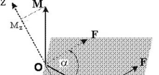
This parameter can be found and displayed as the formula Ф = BS cos α, in which α is the angle between the normal direction to the surface S and the magnetic induction vector B. Based on this formula, it is possible to determine the magnetic flux with a maximum value at which cos α = 1 , and the position of the vector B will become parallel to the normal perpendicular to the surface S. Conversely, the magnetic flux will be minimal if the vector B is located perpendicular to the normal.
In this version, the vector lines simply slide along the plane and do not cross it. That is, the flux is taken into account only along the lines of the magnetic induction vector crossing a specific surface.
To find this value, weber or volt-seconds are used (1 Wb \u003d 1 V x 1 s). This parameter can be measured in other units. The smaller value is the maxwell, which is 1 Wb = 10 8 µs or 1 µs = 10 -8 Wb.
Magnetic field energy and magnetic induction flux
If you skip the conductor electricity, then a magnetic field with energy is formed around it. Its origin is associated with the electric power of the current source, which is partially consumed to overcome the EMF of self-induction that occurs in the circuit. This is the so-called self-energy of the current, due to which it is formed. That is, the energies of the field and current will be equal to each other.
The value of the self-energy of the current is expressed by the formula W \u003d (L x I 2) / 2. This definition is considered equal to the work done by a current source that overcomes the inductance, that is, the EMF of self-induction and creates a current in electrical circuit. When the current stops acting, the energy of the magnetic field does not disappear without a trace, but is released, for example, in the form of an arc or spark.

magnetic flux, arising in the field, is also known as a magnetic induction flux with a positive or negative value, whose direction is conventionally indicated by a vector. As a rule, this flow passes through a circuit through which an electric current flows. With a positive direction of the normal relative to the contour, the direction of current movement is a value determined in accordance with . In this case, the magnetic flux created by the circuit with electric current, and passing through this circuit, will always have a value greater than zero. Practical measurements also point to this.
The magnetic flux is usually measured in units established by the international SI system. This is the already known Weber, which is the magnitude of the flow passing through a plane with an area of 1 m2. This surface is placed perpendicular to the magnetic field lines with a uniform structure.
This concept is well described by the Gauss theorem. It reflects the absence of magnetic charges, so the induction lines are always represented as closed or going to infinity without beginning or end. That is, the magnetic flux passing through any kind of closed surfaces is always zero.
Magnetic flux (flux of magnetic induction lines)
through the contour is numerically equal to the product of the modulus of the magnetic induction vector and the area bounded by the contour, and the cosine of the angle between the direction of the magnetic induction vector and the normal to the surface bounded by this contour. ![]()
The formula for the work of the Ampère force when a straight conductor with direct current moves in a uniform magnetic field.
![]()
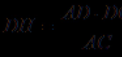
Thus, the work of the Ampere force can be expressed in terms of the current strength in the conductor being moved and the change in the magnetic flux through the circuit in which this conductor is included: ![]()
Loop inductance.
![]() Inductance
- physical a value numerically equal to the EMF of self-induction that occurs in the circuit when the current strength changes by 1 ampere in 1 second.
Inductance
- physical a value numerically equal to the EMF of self-induction that occurs in the circuit when the current strength changes by 1 ampere in 1 second.
Also, the inductance can be calculated by the formula:
 where F is the magnetic flux through the circuit, I is the current strength in the circuit.
SI units for inductance:
The energy of the magnetic field.
 The magnetic field has energy. Just as a charged capacitor has a supply of electrical energy, a coil with current flowing through its coils has a supply of magnetic energy.
Electromagnetic induction.
Electromagnetic induction - the phenomenon of the occurrence of an electric current in a closed circuit with a change in the magnetic flux passing through it.
Faraday's experiments. Explanation electromagnetic induction.
If you bring a permanent magnet to the coil or vice versa (Fig. 3.1), then an electric current will appear in the coil. The same thing happens with two closely spaced coils: if an alternating current source is connected to one of the coils, an alternating current will also appear in the other, but this effect is best manifested if the two coils are connected by a core
According to Faraday's definition, the following is common to these experiments: if the flow of the induction vector penetrating a closed, conducting circuit changes, then an electric current appears in the circuit.
This phenomenon is called the phenomenon electromagnetic induction , and the current induction. In this case, the phenomenon is completely independent of the method of changing the flux of the magnetic induction vector.
E.m.f. formula electromagnetic induction.
EMF induction in a closed loop is directly proportional to the rate of change of the magnetic flux through the area bounded by this loop.
Lenz's rule.
Lenz's rule
The induction current arising in a closed circuit counteracts the change in the magnetic flux with which it is caused by its magnetic field. 
Self-induction, its explanation.
self induction- the phenomenon of the occurrence of induction EMF in an electric circuit as a result of a change in current strength.
 Closing the circuit
When a circuit is closed, the current increases, which causes an increase in the magnetic flux in the coil, a vortex electric field arises, directed against the current, i.e. an EMF of self-induction occurs in the coil, which prevents the current from rising in the circuit (the vortex field slows down the electrons).
As a result, L1 lights up later than L2.
 Open circuit
When the electric circuit is opened, the current decreases, there is a decrease in the m.flow in the coil, a vortex electric field appears, directed like a current (tending to maintain the same current strength), i.e. A self-inductive emf appears in the coil, which maintains the current in the circuit.
As a result, L flashes brightly when turned off.
in electrical engineering, the phenomenon of self-induction manifests itself when the circuit is closed (the electric current increases gradually) and when the circuit is opened (the electric current does not disappear immediately).
E.m.f. formula self-induction.
 EMF of self-induction prevents the increase in current strength when the circuit is turned on and the decrease in current strength when the circuit is opened.
The first and second provisions of the theory electromagnetic field Maxwell.
![]() 1. Any displaced electric field generates a vortex magnetic field. An alternating electric field was named by Maxwell because, like an ordinary current, it induces a magnetic field. The vortex magnetic field is generated both by conduction currents Ipr (moving electric charges) and displacement currents (displaced electric field E).
1. Any displaced electric field generates a vortex magnetic field. An alternating electric field was named by Maxwell because, like an ordinary current, it induces a magnetic field. The vortex magnetic field is generated both by conduction currents Ipr (moving electric charges) and displacement currents (displaced electric field E).
Maxwell's first equation
 2. Any displaced magnetic field generates a vortex electric field (the basic law of electromagnetic induction).
Maxwell's second equation:
Electromagnetic radiation.
electromagnetic waves, electromagnetic radiation- propagating in space perturbation (change of state) of the electromagnetic field.
3.1. Wave
are vibrations propagating in space over time.
mechanical waves can only propagate in some medium (substance): in a gas, in a liquid, in a solid. Waves are generated by oscillating bodies that create a deformation of the medium in the surrounding space. A necessary condition for the appearance of elastic waves is the occurrence at the moment of perturbation of the medium of forces preventing it, in particular, elasticity. They tend to bring neighboring particles closer together when they move apart, and push them away from each other when they approach each other. Elastic forces, acting on particles far from the source of perturbation, begin to unbalance them. Longitudinal waves characteristic only of gaseous and liquid media, but transverse- also to solids: the reason for this is that the particles that make up these media can move freely, since they are not rigidly fixed, in contrast to solids. Accordingly, transverse vibrations are fundamentally impossible.
Longitudinal waves arise when the particles of the medium oscillate, orienting themselves along the propagation vector of the perturbation. Transverse waves propagate in a direction perpendicular to the impact vector. In short: if in a medium the deformation caused by a perturbation manifests itself in the form of shear, tension and compression, then we are talking about a solid body, for which both longitudinal and transverse waves are possible. If the appearance of a shift is impossible, then the medium can be any.
Each wave propagates at a certain speed. Under wave speed understand the propagation speed of the disturbance. Since the speed of the wave is a constant value (for a given medium), the distance traveled by the wave is equal to the product of the speed and the time of its propagation. Thus, to find the wavelength, it is necessary to multiply the speed of the wave by the period of oscillations in it:

Wavelength - the distance between two points in space closest to each other at which oscillations occur in the same phase. The wavelength corresponds to the spatial period of the wave, that is, the distance that a point with a constant phase "travels" in a time interval equal to the period of oscillation, therefore
![]()
wave number(also called spatial frequency) is the ratio 2 π radian to wavelength: spatial analogue of circular frequency.
Definition: the wave number k is the growth rate of the phase of the wave φ along the spatial coordinate.
3.2. plane wave - a wave whose front has the shape of a plane.
The plane wave front is unlimited in size, the phase velocity vector is perpendicular to the front. A plane wave is a particular solution of the wave equation and a convenient model: such a wave does not exist in nature, since the front of a plane wave begins at and ends at , which, obviously, cannot be.
The equation of any wave is the solution differential equation called wave. The wave equation for the function is written as:
![]() where
where
· - Laplace operator;
· - desired function;
· - radius of the vector of the desired point;
- wave speed;
· - time.
wave surface is the locus of points that are perturbed by the generalized coordinate in the same phase. special case wave surface - wave front.
BUT) plane wave
- this is a wave, the wave surfaces of which are a set of planes parallel to each other. 
B) spherical wave is a wave whose wave surfaces are a collection of concentric spheres.
Ray- line, normal and wave surface. Under the direction of propagation of waves understand the direction of the rays. If the propagation medium of the wave is homogeneous and isotropic, the rays are straight lines (moreover, if the wave is plane - parallel straight lines).
The concept of a ray in physics is usually used only in geometric optics and acoustics, since the manifestation of effects that are not studied in these areas, the meaning of the concept of a ray is lost.
3.3. Energy characteristics of the wave
The medium in which the wave propagates has mechanical energy, made up of energies oscillatory motion all of its particles. The energy of one particle with mass m 0 is found by the formula: E 0 = m 0 Α 2 w 2/2. The volume unit of the medium contains n = p/m 0 particles (ρ is the density of the medium). Therefore, a unit volume of the medium has the energy w р = nЕ 0 = ρ Α 2 w 2 /2.
Bulk energy density(W p) is the energy of the oscillatory motion of the particles of the medium contained in a unit of its volume:
Energy flow(Ф) - a value equal to the energy carried by the wave through a given surface per unit time:
Wave intensity or energy flux density(I) - a value equal to the energy flux carried by the wave through a single area, perpendicular to the direction of wave propagation:
3.4. electromagnetic wave
electromagnetic wave- the process of electromagnetic field propagation in space.
Occurrence condition electromagnetic waves. Changes in the magnetic field occur when the current strength in the conductor changes, and the current strength in the conductor changes with a change in the speed of movement electric charges in it, i.e., when charges move with acceleration. Therefore, electromagnetic waves should arise during the accelerated movement of electric charges. At a charge rate of zero, there is only an electric field. At a constant charge rate, an electromagnetic field is generated. With the accelerated movement of the charge, an electromagnetic wave is emitted, which propagates in space at a finite speed.
Electromagnetic waves propagate in matter with a finite speed. Here ε and μ are the dielectric and magnetic permeability of the substance, ε 0 and μ 0 are the electrical and magnetic constants: ε 0 \u003d 8.85419 10 -12 F / m, μ 0 \u003d 1.25664 10 -6 Gn / m.
Velocity of electromagnetic waves in vacuum (ε = μ = 1):

Main Features electromagnetic radiation is considered to be the frequency, wavelength and polarization. The wavelength depends on the propagation speed of the radiation. The group velocity of propagation of electromagnetic radiation in vacuum is equal to the speed of light, in other media this speed is less.
Electromagnetic radiation is usually divided into frequency ranges (see table). There are no sharp transitions between the ranges, they sometimes overlap, and the boundaries between them are conditional. Since the speed of propagation of radiation is constant, the frequency of its oscillations is strictly related to the wavelength in vacuum.

Wave interference. coherent waves. Wave coherence conditions.
Optical path length (OPL) of light. Relation between the difference of the r.d.p. waves with a phase difference of oscillations caused by waves.
The amplitude of the resulting oscillation in the interference of two waves. Conditions for maxima and minima of the amplitude during the interference of two waves.
Interference fringes and interference pattern on a flat screen illuminated by two narrow long parallel slits: a) red light, b) white light.
1) WAVE INTERFERENCE- such an imposition of waves, in which their mutual amplification, stable in time, occurs at some points in space and attenuation at others, depending on the ratio between the phases of these waves.

The necessary conditions to observe interference:
1) the waves must have the same (or close) frequencies so that the picture resulting from the superposition of the waves does not change in time (or does not change very quickly so that it can be registered in time);
2) waves must be unidirectional (or have a close direction); two perpendicular waves will never interfere (try adding two perpendicular sinusoids together!). In other words, the added waves must have the same wave vectors (or closely directed).
Waves for which these two conditions are satisfied are called COHERENT. The first condition is sometimes called temporal coherence, second - spatial coherence.
Consider as an example the result of adding two identical unidirectional sinusoids. We will vary only their relative shift. In other words, we add two coherent waves that differ only in their initial phases (either their sources are shifted relative to each other, or both).
If the sinusoids are located so that their maxima (and minima) coincide in space, their mutual amplification will occur.
If the sinusoids are shifted relative to each other by half a period, the maxima of one will fall on the minima of the other; sinusoids will destroy each other, that is, their mutual weakening will occur.
Mathematically it looks like this. We add two waves:
here x 1 and x 2- distances from the wave sources to the point in space where we observe the result of the overlay. The square of the amplitude of the resulting wave (proportional to the intensity of the wave) is given by:
The maximum of this expression is 4A2, minimum - 0; it all depends on the difference initial phases and from the so-called wave path difference :
When at a given point in space, an interference maximum will be observed, at - an interference minimum.
In our simple example the sources of the waves and the point in space where we observe the interference are on the same straight line; along this straight line the interference pattern is the same for all points. If we shift the observation point away from the straight line connecting the sources, we will find ourselves in a region of space where the interference pattern changes from point to point. In this case, we will observe the interference of waves with equal frequencies and close wave vectors.
2)1. The optical path length is the product of the geometric length d of the path of a light wave in a given medium and the absolute refractive index of this medium n.
2. The phase difference of two coherent waves from one source, one of which passes the path length in a medium with an absolute refractive index, and the other passes the path length in a medium with an absolute refractive index:
![]()
where , , λ is the wavelength of light in vacuum.
3) The amplitude of the resulting oscillation depends on a quantity called stroke difference waves.


If the path difference is equal to an integer number of waves, then the waves arrive at the point in phase. When added together, the waves reinforce each other and give an oscillation with a double amplitude.


If the path difference is equal to an odd number of half-waves, then the waves arrive at point A in antiphase. In this case, they cancel each other, the amplitude of the resulting oscillation is zero.


At other points in space, a partial amplification or weakening of the resulting wave is observed.
4) Jung's experience
In 1802 an English scientist Thomas Young set up an experiment in which he observed the interference of light. Light out narrow gap S, fell on the screen with two closely spaced slits S1 and S2. Passing through each of the slits, the light beam expanded, and on a white screen, the light beams that passed through the slits S1 and S2, overlapped. In the region of overlapping light beams, an interference pattern was observed in the form of alternating light and dark stripes.

The implementation of light interference from conventional light sources.
Interference of light on a thin film. Conditions for maxima and minima of light interference on a film in reflected and transmitted light.
Interference fringes of equal thickness and interference fringes of equal slope.
1) The phenomenon of interference is observed in a thin layer of immiscible liquids (kerosene or oil on the surface of water), in soap bubbles, gasoline, on butterfly wings, in tint colors, etc.
2)  Interference occurs when an initial beam of light splits into two beams as it passes through a thin film, such as the film deposited on the lens surface of coated lenses. A beam of light, passing through a film of thickness , will be reflected twice - from its inner and outer surfaces. The reflected rays will have a constant phase difference equal to twice the thickness of the film, which is why the rays become coherent and will interfere. Complete extinction of the rays will occur at , where is the wavelength. If a
 ![]() nm, then the film thickness is 550:4=137.5 nm.
nm, then the film thickness is 550:4=137.5 nm.
MAGNETIC FLUX
MAGNETIC FLUX(symbol F), a measure of the strength and extent of the MAGNETIC FIELD. The flow through area A at right angles to the same magnetic field is Ф=mNA, where m is the magnetic PERMEABILITY of the medium, and H is the intensity of the magnetic field. The magnetic flux density is the flux per unit area (symbol B), which is equal to H. The change in magnetic flux through electrical conductor induces ELECTRIC DRIVE FORCE.
Scientific and technical encyclopedic dictionary.
See what "MAGNETIC FLOW" is in other dictionaries:
The flow of the magnetic induction vector B through any surface. The magnetic flux through a small area dS, within which the vector B is unchanged, is equal to dФ = ВndS, where Bn is the projection of the vector onto the normal to the area dS. Magnetic flux Ф through the final ... ... Large encyclopedic Dictionary
- (flux of magnetic induction), flux Ф of the magnetic vector. induction B through c.l. surface. M. p. dФ through a small area dS, within which the vector B can be considered unchanged, is expressed by the product of the size of the area and the projection Bn of the vector onto ... ... Physical Encyclopedia
magnetic flux- A scalar value equal to the flux of magnetic induction. [GOST R 52002 2003] magnetic flux The flux of magnetic induction through a surface perpendicular to the magnetic field, defined as the product of magnetic induction at a given point and the area ... ... Technical Translator's Handbook
MAGNETIC FLUX- flux Ф of the magnetic induction vector (see (5)) В through the surface S, normal to the vector В in a uniform magnetic field. The unit of magnetic flux in SI (see) ... Great Polytechnic Encyclopedia
A value that characterizes the magnetic effect on a given surface. M. p. is measured by the number of magnetic lines of force passing through a given surface. Technical railway dictionary. M .: State transport ... ... Technical railway dictionary
magnetic flux- a scalar quantity equal to the flux of magnetic induction... Source: ELEKTROTEHNIKA. TERMS AND DEFINITIONS OF BASIC CONCEPTS. GOST R 52002 2003 (approved by the Decree of the State Standard of the Russian Federation of 01/09/2003 N 3 st) ... Official terminology
The flow of the magnetic induction vector B through any surface. The magnetic flux through a small area dS, within which the vector B is unchanged, is equal to dФ = BndS, where Bn is the projection of the vector onto the normal to the area dS. Magnetic flux Ф through the final ... ... encyclopedic Dictionary
Classical electrodynamics ... Wikipedia
magnetic flux- , flux of magnetic induction flux of the vector of magnetic induction through any surface. For a closed surface, the total magnetic flux is zero, which reflects the solenoid nature of the magnetic field, i.e., the absence in nature of ... Encyclopedic Dictionary of Metallurgy
magnetic flux- 12. Magnetic flux Flux of magnetic induction Source: GOST 19880 74: Electrical engineering. Basic concepts. Terms and definitions original document 12 magnetic on ... Dictionary-reference book of terms of normative and technical documentation
Books
- , Mitkevich V. F. Category: Mathematics Publisher: YoYo Media, Manufacturer: YoYo Media,
- Magnetic flux and its transformation, Mitkevich V.F., This book contains a lot that is not always paid due attention when it comes to magnetic flux, and that has not yet been sufficiently clearly expressed or has not been ... Category: Mathematics and Science Series: Publisher:
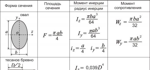
Among the general industrial ones used to account for products and raw materials, commodity, automobile, wagon, trolley, etc. are common. Technological ones are used to weigh products during production in technologically continuous and periodic processes. Laboratory ones are used to determine the moisture content of materials and semi-finished products, to conduct a physicochemical analysis of raw materials, and for other purposes. There are technical, exemplary, analytical and microanalytical.
Can be divided into a number of types depending on physical phenomena on which their principle of action is based. The most common devices are magnetoelectric, electromagnetic, electrodynamic, ferrodynamic and induction systems.
The scheme of the device of the magnetoelectric system is shown in fig. one.
The fixed part consists of a magnet 6 and a magnetic circuit 4 with pole pieces 11 and 15, between which a strictly centered steel cylinder 13 is installed. In the gap between the cylinder and the pole pieces, where a uniform radial direction is concentrated, there is a frame 12 made of thin insulated copper wire.
The frame is fixed on two axes with cores 10 and 14, resting against thrust bearings 1 and 8. Opposing springs 9 and 17 serve as current leads connecting the frame winding with the electrical circuit and input terminals of the device. Arrow 3 with balance weights 16 and an opposing spring 17 connected to the corrector lever 2 are fixed on the axis 4.
01.04.2019
1. The principle of active radar.
2. Pulse radar. Principle of operation.
3. Basic timing of the operation of a pulsed radar.
4. Types of radar orientation.
5. Formation of a sweep on the PPI radar.
6. The principle of operation of the induction log.
7. Types of absolute lags. Hydroacoustic Doppler log.
8. Flight data recorder. Description of work.
9. Purpose and principle of AIS operation.
10.Transmitted and received AIS information.
11. Organization of radio communication in AIS.
12. The composition of the AIS ship equipment.
13. Structural diagram of the ship's AIS.
14. The principle of operation of the GPS SNS.
15. Essence of GPS differential mode.
16.Sources of errors in GNSS.
17. Structural diagram of the GPS receiver.
18. The concept of ECDIS.
19. ENC classification.
20. Appointment and properties of the gyroscope.
21. The principle of operation of the gyrocompass.
22. The principle of operation of a magnetic compass.
Connecting cables- a technological process for obtaining an electrical connection of two cable segments with restoration at the junction of all protective and insulating sheaths of the cable and screen braids.
Before connecting the cables, measure the insulation resistance. For unshielded cables, for ease of measurement, one output of the megohmmeter is connected in turn to each core, and the second to the remaining cores connected to each other. The insulation resistance of each shielded core is measured when the leads are connected to the core and its screen. , obtained as a result of measurements, should not be less than the normalized value established for this brand of cable.
Having measured the insulation resistance, they proceed to the establishment or numbering of the cores, or the directions of the lay, which are indicated by arrows on the temporarily fixed tags (Fig. 1).
Having finished preparatory work, you can start cutting cables. The geometry of the cutting of the connections of the ends of the cables is modified in order to ensure the convenience of restoring the insulation of the cores and the sheath, and for multi-core cables, also to obtain acceptable dimensions for the junction of the cables.
METHODOLOGICAL AID FOR PRACTICAL WORK: "OPERATION OF SPP COOLING SYSTEMS"
BY DISCIPLINE: " OPERATION OF POWER PLANTS AND SAFE WATCHING IN THE ENGINE ROOM»
COOLING SYSTEM OPERATION
Purpose of the cooling system:
- heat removal from the main engine;
- heat removal from auxiliary equipment;
- heat supply to the Shelter and other equipment (GD before start-up, VDG maintained in "hot" reserve, etc.);
- receiving and filtering outboard water;
- blowing out kingston boxes in summer from clogging with jellyfish, algae, mud, in winter - from ice;
- ensuring the operation of ice boxes, etc.
|
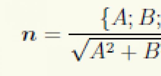
Flux of magnetic induction vector AT (magnetic flux) through a small surface area dS called scalar physical quantity equal to |
Here , is the unit vector of the normal to the area with area dS, In n- vector projection AT to the direction of the normal, - the angle between the vectors AT and n (Fig. 6.28).

Rice. 6.28. Flux of the magnetic induction vector through the pad
Magnetic flux F B through an arbitrary closed surface S equals
|
|
The absence of magnetic charges in nature leads to the fact that the lines of the vector AT have no beginning or end. Therefore, the flow of the vector AT through a closed surface must be equal to zero. Thus, for any magnetic field and an arbitrary closed surface S the condition
|
|
Formula (6.28) expresses Ostrogradsky - Gauss theorem for vector :
We emphasize again: this theorem is mathematical expression the fact that in nature there are no magnetic charges on which the lines of magnetic induction would begin and end, as was the case in the case of tension electric field E point charges.
This property essentially distinguishes a magnetic field from an electric one. The lines of magnetic induction are closed, so the number of lines entering a certain volume of space is equal to the number of lines leaving this volume. If the incoming fluxes are taken with one sign, and the outgoing ones with another sign, then the total flux of the magnetic induction vector through the closed surface will be equal to zero.

Rice. 6.29. W. Weber (1804–1891) – German physicist
The difference between a magnetic field and an electrostatic one also manifests itself in the value of a quantity that we call circulation- the integral of the vector field along a closed path. In electrostatics, the integral is equal to zero
taken along an arbitrary closed contour. This is due to the potentiality of an electrostatic field, that is, the fact that the work done to move a charge in an electrostatic field does not depend on the path, but only on the position of the start and end points.
Let's see how things stand with a similar value for a magnetic field. Let us take a closed circuit, covering the direct current, and calculate for it the circulation of the vector AT , i.e
As was obtained above, the magnetic induction created by a straight conductor with current at a distance R from the conductor, is equal to
Let us consider the case when the circuit enclosing the forward current lies in a plane perpendicular to the current and is a circle with a radius R centered on the conductor. In this case, the circulation of the vector AT along this circle is equal to
|
It can be shown that the result for the circulation of the magnetic induction vector does not change with continuous deformation of the contour, if during this deformation the contour does not cross the streamlines. Then, due to the principle of superposition, the circulation of the magnetic induction vector along a path covering several currents is proportional to their algebraic sum (Fig. 6.30)
|

Rice. 6.30. Closed loop (L) with defined bypass direction.
Shown are currents I 1 , I 2 and I 3 that create a magnetic field.
The contribution to the circulation of the magnetic field along the contour (L) is given only by currents I 2 and I 3
If the selected circuit does not cover currents, then the circulation through it is equal to zero.
When calculating algebraic sum currents, the sign of the current should be taken into account: we will consider positive the current, the direction of which is related to the direction of bypass along the contour by the rule of the right screw. For example, the current contribution I 2 into the circulation is negative, and the contribution of the current I 3 - positive (Fig. 6.18). Using the relation
between current strength I through any closed surface S and current density , for the circulation vector AT can be written
|
where S- any closed surface based on a given contour L.
Such fields are called eddy. Therefore, a potential cannot be introduced for a magnetic field, as was done for the electric field of point charges. The difference between the potential and vortex fields can be most clearly represented by the pattern of field lines. lines of force electrostatic fields are like hedgehogs: they start and end on charges (or go to infinity). The lines of force of the magnetic field never resemble "hedgehogs": they are always closed and cover the currents.
To illustrate the application of the circulation theorem, let us find by another method the already known magnetic field of an infinite solenoid. Take a rectangular contour 1-2-3-4 (Fig. 6.31) and calculate the circulation of the vector AT along this contour

Rice. 6.31. Application of the circulation theorem B to the determination of the magnetic field of a solenoid
The second and fourth integrals are equal to zero due to the perpendicularity of the vectors and
We have reproduced the result (6.20) without integrating the magnetic fields from individual turns.
The result obtained (6.35) can be used to find the magnetic field of a thin toroidal solenoid (Fig. 6.32).

Rice. 6.32. Toroidal Coil: lines of magnetic induction are closed inside the coil and are concentric circles. They are directed so that looking along them, we would see the current in the coils circulating clockwise. One of the lines of induction of some radius r 1 ≤ r< r 2 изображена на рисунке