THE LAW OF ELECTROMAGNETIC INDUCTION. LENTZ RULE
In 1831, the English physicist M. Faraday in his experiments discovered the phenomenon electromagnetic induction. Then the Russian scientist E.Kh. Lenz and B.S. Jacobi.
At present, many devices are based on the phenomenon of electromagnetic induction, for example, in a motor or generator electric current, in transformers, radios, and many other devices.
Electromagnetic induction is the phenomenon of the occurrence of current in a closed conductor, when passing through it magnetic flux.
That is, thanks to this phenomenon, we can transform mechanical energy into electrical. Before the discovery of this phenomenon, people did not know about the methods of obtaining electric current, except for electroplating.
When the conductor is affected magnetic field, an EMF arises in it, which can be quantitatively expressed through the law of electromagnetic induction.
Law of electromagnetic induction
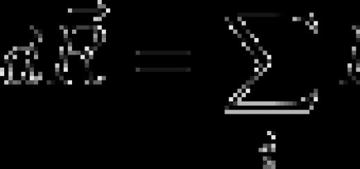
The electromotive force induced in a conducting circuit is equal to the rate of change of the magnetic flux interlocking with this circuit.
In a coil that has several turns, the total emf depends on the number of turns n:
The emf excited in the circuit creates a current. Most simple example current in the conductor is a coil through which a permanent magnet passes. The direction of the induced current can be determined using the Lenz rule.
Lenz's rule
The current induced by a change in the magnetic field passing through the circuit, with its magnetic field, prevents this change.
In the case when we introduce a magnet into the coil, the magnetic flux in the circuit increases, which means that the magnetic field created by the induced current, according to Lenz's rule, is directed against the increase in the field of the magnet. To determine the direction of the current, you need to look at the magnet from the north pole. From this position, we will screw the gimlet in the direction of the magnetic field of the current, that is, towards the north pole. The current will move in the direction of rotation of the gimlet, that is, clockwise.
In the case when we remove the magnet from the coil, the magnetic flux in the circuit decreases, which means that the magnetic field created by the induced current is directed against the decrease in the magnet field. To determine the direction of the current, you need to unscrew the gimlet, the direction of rotation of the gimlet will indicate the direction of the current in the conductor - counterclockwise.
An electric generator is a device in which non-electrical forms of energy (mechanical, chemical, thermal) are converted into electrical energy.
Classification of electromechanical generators
By type of prime mover:
Turbogenerator - an electrical generator driven by a steam turbine or gas turbine engine;
Hydrogenerator - an electric generator driven by a hydraulic turbine;
Diesel generator - an electric generator driven by a diesel engine;
Wind generator - an electric generator that converts the kinetic energy of the wind into electricity;
By type of output electric current
Three-phase generator with star windings
With the inclusion of windings in a triangle
By way of excitation
With permanent magnet excitation
with external stimulation
With self-excitation
With sequential excitation
With parallel excitation
With mixed excitement
According to the principle of operation, generators can be synchronous or asynchronous.
Asynchronous generators are structurally simple and inexpensive to manufacture, more resistant to short circuit currents and overloads. An asynchronous electric generator is ideal for powering a resistive load: incandescent lamps, electric heaters, electronics, electric burners, etc. But even a short-term overload is unacceptable for them, therefore, when connecting electric motors, a non-electronic type of welding machine, power tools and other inductive loads, there is a margin for power should be at least three times, and preferably four times.
The synchronous generator is perfect for inductive consumers with high starting currents. They are capable of withstanding a fivefold current overload for one second.
The principle of operation of the current generator
The generator works on the basis of Faraday's law of electromagnetic induction - an electromotive force (EMF) is induced in a rectangular circuit (wire frame) rotating in a uniform magnetic field.
EMF also occurs in a fixed rectangular frame if a magnet is rotated in it.
The simplest generator is a rectangular frame placed between 2 magnets with different poles. In order to remove the voltage from the rotating frame, slip rings are used.
The car generator consists of a body and two covers with holes for ventilation. The rotor rotates in 2 bearings and is driven by a pulley. At its core, the rotor is an electromagnet consisting of one winding. Current is supplied to it using two copper rings and graphite brushes, which are connected to an electronic relay-regulator. He is responsible for ensuring that the voltage output by the generator is always within the acceptable range of 12 volts with tolerances and does not depend on the speed of the pulley. The relay-regulator can be either built into the generator housing or located outside it.
The stator consists of three copper windings connected to each other in a triangle. A rectifier bridge of 6 semiconductor diodes is connected to their connection points, which convert the voltage from AC to DC.
A gasoline generator consists of an engine and a current generator that directly drives it, which can be either synchronous or asynchronous.
The engine is equipped with systems: starting, fuel injection, cooling, lubrication, speed stabilization. Vibration and noise are absorbed by the muffler, vibration dampers and shock absorbers.
Alternating electric current
Electromagnetic oscillations, like mechanical ones, are of two types: free and forced.
Free electromagnetic oscillations, always damped oscillations. Therefore, they are almost never used in practice. While forced vibrations are used everywhere and everywhere. Every day we can observe these fluctuations.
All our apartments are lit with alternating current. Alternating current is nothing but forced electromagnetic oscillations. The current and voltage will change over time according to the harmonic law. Fluctuations, such as voltage, can be detected by applying voltage from the outlet to the oscilloscope.
A sine wave will appear on the oscilloscope screen. You can calculate the frequency of the alternating current. It will equal the frequency electromagnetic oscillations. The standard frequency for industrial alternating current is assumed to be 50 Hz. That is, in 1 second, the direction of the current in the outlet changes 50 times. US industrial networks use 60 Hz.
A change in voltage at the ends of the circuit will cause a change in the current strength in the circuit of the oscillatory circuit. However, it should be understood that the change electric field throughout the chain does not occur instantly.
But since this time is much less than the period of voltage fluctuation at the ends of the circuit, it is usually believed that the electric field in the circuit changes immediately, as the voltage at the ends of the circuit changes.
The alternating voltage in the outlet is generated by generators in power plants. The simplest generator can be considered a wire frame that rotates in a uniform magnetic field.
The magnetic flux penetrating the contour will constantly change and will be proportional to the cosine of the angle between the magnetic induction vector and the normal to the frame. If the frame rotates evenly, then the angle will be proportional to the time.
Therefore, the magnetic flux will change according to the harmonic law:
Ф = B*S*cos(ω*t)
The rate of change of the magnetic flux, taken with the opposite sign, according to the EMP law, will be equal to the EMF of induction.
Ei \u003d -Ф ' \u003d Em * sin (ω * t).
If an oscillatory circuit is connected to the frame, then angular velocity rotation of the frame will determine the frequency of voltage fluctuations on different areas circuits and currents. In what follows, we will consider only forced electromagnetic oscillations.
They are described by the following formulas:
u = Um*sin(ω*t),
u = Um*cos(ω*t)
Here Um is the amplitude of voltage fluctuations. Voltage and current change with the same frequency ω. But voltage fluctuations will not always coincide with current fluctuations, so it is better to use a more general formula:
I \u003d Im * sin (ω * t + φ), where Im is the amplitude of current oscillations, and φ is the phase shift between current and voltage oscillations.
AC current and voltage parameters
The magnitude of alternating current, like voltage, is constantly changing with time. Quantitative indicators for measurements and calculations use their following parameters:
Period T - the time during which there is one complete cycle of current change in both directions relative to zero or the average value.
The frequency f is the reciprocal of the period, equal to the number of periods in one second. One period per second is one hertz (1 Hz)
f = 1/T
Cyclic frequency ω - angular frequency equal to the number of periods in 2π seconds.
ω = 2πf = 2π/T
It is usually used when calculating current and voltage of a sinusoidal form. Then, within the period, one can not consider frequency and time, but make calculations in radians or degrees. T = 2π = 360°
The initial phase ψ is the value of the angle from zero (ωt = 0) to the beginning of the period. It is measured in radians or degrees. Shown in the figure for the blue sinusoidal current graph. The initial phase can be positive or negative, respectively to the right or left of zero on the graph.
Instantaneous value - the value of voltage or current measured relative to zero at any selected time t.
i = i(t); u = u(t)
The sequence of all instantaneous values in any time interval can be considered as a function of the change in current or voltage over time. For example, a sinusoidal current or voltage can be expressed as a function:
i = Iampsin(ωt); u = Uampsin(ωt)
Taking into account the initial phase:
i = Iampsin(ωt + ψ); u = Uampsin(ωt + ψ)
Here Iamp and Uamp are the amplitude values of current and voltage.
Amplitude value - the maximum instantaneous value in absolute value for the period.
Iamp = max|i(t)|; Uamp = max|u(t)|
It can be positive or negative depending on the position relative to zero. Often, instead of the amplitude value, the term current (voltage) amplitude is used - the maximum deviation from zero.
D / s
Report on the topic (at the student's choice)
Production and transmission of electricity
Transformer. Transmission of electricity over a distance
Energy saving in everyday lifeThe first experiments on the transmission of electricity at a distanceTransformer efficiency. Device and workUse of electricityTurbine generator. Device and work
Hydrogenerator. Device and work
Diesel generator. Device and work
Wind generator. Device and work
Tasks for independent solution
Faraday's law of EM induction.
1. The magnetic flux inside a coil with a number of turns equal to 400 changed from 0.1 Wb to 0.9 Wb in 0.2 s. Determine the emf induced in the coil.
2. Determine the magnetic flux passing through a rectangular area with sides of 20x40 cm, if it is placed in a uniform magnetic field with an induction of 5 T at an angle of 60 ° to the lines of magnetic induction of the field.
3. How many turns should the coil have so that when the magnetic flux inside it changes from 0.024 to 0.056 Wb in 0.32 s, an average emf is created in it. 10 V?
EMF of induction in moving conductors.
1. Determine the induction EMF at the ends of the wings of the An-2 aircraft, having a length of 12.4 m, if the aircraft speed in horizontal flight is 180 km/h, and the vertical component of the Earth's magnetic field induction vector is 0.5 10-4 T.
2. Find the EMF of induction on the wings of a Tu-204 aircraft, having a length of 42 m, flying horizontally at a speed of 850 km/h, if the vertical component of the Earth's magnetic field induction vector is 5·10-5 T.
EMF self-induction
1. A magnetic flux of 0.015 Wb occurs in the coil when a current of 5.0 A passes through its turns. How many turns does the coil contain if its inductance is 60 mH?
2. How many times will the inductance of a coil without a core change if the number of turns in it is doubled?
3. What emf. self-induction will occur in a coil with an inductance of 68 mH, if a current of 3.8 A disappears in it in 0.012 s?
4. Determine the inductance of the coil if, when the current in it is weakened by 2.8 A in 62 ms, an average emf appears in the coil. self-induction 14 V.
5. How long does it take for a coil with an inductance of 240 mH to increase the current from zero to 11.4 A if an average emf occurs in this case? self-induction 30 V?
Electromagnetic field energy
1. A current of 20 A flows through a coil with an inductance of 0.6 H. What is the energy of the magnetic field of the coil? How will this energy change when the current is doubled? 3 times?
2. What strength of current must be passed through the winding of a choke with an inductance of 0.5 Gn so that the field energy is 100 J?
3. The energy of the magnetic field of which coil is greater and how many times if the first has the characteristics: I1=10A, L1=20 H, the second: I2=20A, L2=10 H?
4. Determine the energy of the magnetic field of the coil, in which at a current of 7.5 A the magnetic flux is 2.3 10-3 Wb. The number of turns in the coil is 120.
5. Determine the inductance of the coil if, at a current of 6.2 A, its magnetic field has an energy of 0.32 J.
6. The magnetic field of a coil with an inductance of 95 mH has an energy of 0.19 J. What is the current strength in the coil?
In this lesson, the topic of which is: “Lenz's rule. The law of electromagnetic induction, we will learn general rule, allowing to determine the direction of the induction current in the circuit, established in 1833 by E.X. Lenz. We will also consider an experiment with aluminum rings, which clearly demonstrates this rule, and formulate the law of electromagnetic induction
By approaching or moving the magnet away from the solid ring, we change the magnetic flux that permeates the area of the ring. According to the theory of the phenomenon of electromagnetic induction, an inductive electric current must occur in the ring. From the experiments of Ampere it is known that where the current passes, a magnetic field arises. Consequently, the closed ring begins to behave like a magnet. That is, there is an interaction of two magnets (a permanent magnet, which we move, and a closed circuit with current).
Since the system did not respond to the approach of the magnet to the ring with a cut, it can be concluded that the induction current does not occur in an open circuit.
Causes of repulsion or attraction of the ring to the magnet
1. When the magnet approaches
When the pole of the magnet approaches, the ring repels from it. That is, it behaves like a magnet, which has the same pole on our side as the approaching magnet. If we approach the north pole of the magnet, then the magnetic induction vector of the ring with inductive current is directed in the opposite direction relative to the magnetic induction vector of the north pole of the magnet (see Fig. 2).

Rice. 2. Approach of the magnet to the ring
2. When removing the magnet from the ring
When the magnet is removed, the ring trails behind it. Consequently, from the side of the receding magnet, the opposite pole is formed near the ring. The magnetic induction vector of the ring with current is directed in the same direction as the magnetic induction vector of the receding magnet (see Fig. 3).

Rice. 3. Removing the magnet from the ring
From this experiment, we can conclude that when the magnet moves, the ring also behaves like a magnet, the polarity of which depends on whether the magnetic flux penetrating the ring area increases or decreases. If the flux increases, then the magnetic induction vectors of the ring and the magnet are opposite in direction. If the magnetic flux through the ring decreases with time, then the magnetic field induction vector of the ring coincides in direction with the magnet induction vector.
The direction of the induction current in the ring can be determined by the rule right hand. If you point the thumb of your right hand in the direction of the magnetic induction vector, then four bent fingers will indicate the direction of the current in the ring (see Fig. 4).

Rice. 4. Right hand rule
When the magnetic flux penetrating the circuit changes, an induction current arises in the circuit in such a direction as to compensate for the change in the external magnetic flux with its magnetic flux.
If the external magnetic flux increases, then the induction current tends to slow down this increase with its magnetic field. If the magnetic flux decreases, then the inductive current with its magnetic field tends to slow down this decrease.
This feature of electromagnetic induction is expressed by the minus sign in EMF formula induction.
Law of electromagnetic induction
When the external magnetic flux penetrating the circuit changes, an induction current appears in the circuit. In this case, the value of the electromotive force is numerically equal to the rate of change of the magnetic flux, taken with the "-" sign.
Lenz's rule is a consequence of the law of conservation of energy in electromagnetic phenomena.
Bibliography
- Myakishev G.Ya. Physics: Proc. for 11 cells. general education institutions. - M.: Education, 2010.
- Kasyanov V.A. Physics. Grade 11: Proc. for general education institutions. - M.: Bustard, 2005.
- Gendenstein L.E., Dick Yu.I., Physics 11. - M .: Mnemosyne.
Homework
- Questions at the end of paragraph 10 (p. 33) - Myakishev G.Ya. Physics 11 (see list of recommended reading)
- How is the law of electromagnetic induction formulated?
- Why is there a "-" sign in the formula for the law of electromagnetic induction?
- Internet portal Festival.1september.ru ().
- Internet portal Physics.kgsu.ru ().
- Internet portal Youtube.com ().
The phenomenon of electromagnetic induction was discovered by the outstanding English physicist M. Faraday in 1831. It consists in the occurrence of an electric current in a closed conducting circuit with a change in time of the magnetic flux penetrating the circuit.
The magnetic flux Φ through the area S of the contour is called the value
Φ = B S cos α,
Where B is the modulus of the magnetic induction vector, α is the angle between the vector and the normal to the contour plane (Fig. 4.20.1).
Figure 4.20.1.
Magnetic flux through a closed loop. The direction of the normal and the selected positive direction of traversal of the contour are related by the rule of the right gimlet.
The definition of magnetic flux can be easily generalized to the case of an inhomogeneous magnetic field and a non-planar contour. The unit of magnetic flux in the SI system is called the weber (Wb). A magnetic flux equal to 1 Wb is created by a magnetic field with an induction of 1 T, penetrating a flat contour of 1 m2 in the direction of the normal:
1 Wb \u003d 1 T 1 m2.
Faraday experimentally established that when the magnetic flux changes in a conducting circuit, an EMF of induction Eind arises, equal to speed changes in the magnetic flux through the surface bounded by the contour, taken with a minus sign:
Experience shows that the induction current excited in a closed circuit when the magnetic flux changes is always directed in such a way that the magnetic field it creates prevents a change in the magnetic flux that causes the inductive current. This statement is called Lenz's rule (1833).
Rice. 4.20.2 illustrates Lenz's rule on the example of a fixed conducting circuit, which is in a uniform magnetic field, the modulus of induction of which increases with time.
Figure 4.20.2.
Illustration of Lenz's rule. In this example, a ind< 0. Индукционный ток Iинд течет навстречу выбранному положительному направлению обхода контура.
Lenz's rule reflects the experimental fact that ind and always have opposite signs (the minus sign in Faraday's formula). Lenz's rule has a deep physical meaning It expresses the law of conservation of energy.
A change in the magnetic flux penetrating a closed circuit can occur for two reasons.
1. The magnetic flux changes due to the movement of the circuit or its parts in a magnetic field constant in time. This is the case when conductors, and with them free charge carriers, move in a magnetic field. The occurrence of the induction EMF is explained by the action of the Lorentz force on free charges in moving conductors. The Lorentz force plays the role of an outside force in this case.
Consider, as an example, the occurrence of induction EMF in a rectangular circuit placed in a uniform magnetic field perpendicular to the plane of the circuit. Let one of the sides of the contour of length l slide with speed along the other two sides (Fig. 4.20.3).
Figure 4.20.3.
Occurrence of EMF induction in a moving conductor. The component of the Lorentz force acting on a free electron is indicated.
Lorentz force acts on free charges in this section of the contour. One of the components of this force, associated with the transfer velocity of the charges, is directed along the conductor. This component is shown in Fig. 4.20.3. She plays the role of an external force. Its modulus is
The work of the force FL on the path l is equal to
A = FL · l = eυBl.
According to the definition of EMF
In other fixed parts of the contour, the external force is zero. The ratio for ind can be given a familiar form. Over time Δt, the contour area changes by ΔS = lυΔt. The change in the magnetic flux during this time is equal to ΔΦ = BlυΔt. Hence,
In order to set the sign in the formula connecting ind and it is necessary to choose the direction of the normal and the positive direction of the contour traversal, which are consistent with each other according to the rule of the right gimlet, as is done in Fig. 4.20.1 and 4.20.2. If this is done, then it is easy to come to the Faraday formula.
If the resistance of the entire circuit is equal to R, then an inductive current equal to Iind \u003d ind / R will flow through it. During the time Δt, Joule heat will be released on the resistance R (see § 4.11)
The question arises: where does this energy come from, because the Lorentz force does no work! This paradox arose because we took into account the work of only one component of the Lorentz force. When an inductive current flows through a conductor in a magnetic field, free charges are affected by another component of the Lorentz force, associated with relative speed movement of charges along a conductor. This component is responsible for the appearance of the Ampere force. For the case shown in Fig. 4.20.3, the Ampère force modulus is equal to FA = IBl. The Ampere force is directed towards the movement of the conductor; therefore she commits a negative mechanical work. During the time Δt, this work Amex is equal to
A conductor moving in a magnetic field, through which an induction current flows, experiences magnetic braking. The total work of the Lorentz force is zero. Joule heat is released in the circuit either due to the work of an external force that keeps the speed of the conductor unchanged, or due to a decrease in the kinetic energy of the conductor.
2. The second reason for the change in the magnetic flux penetrating the circuit is the change in time of the magnetic field when the circuit is stationary. In this case, the occurrence of the induction EMF can no longer be explained by the action of the Lorentz force. Electrons in a fixed conductor can only be set in motion by an electric field. This electric field is generated by a time-varying magnetic field. The work of this field when moving a single positive charge along a closed circuit is equal to the induction EMF in a stationary conductor. Therefore, the electric field generated by the changing magnetic field is not potential. It is called the vortex electric field. The idea of a vortex electric field was introduced into physics by the great English physicist J. Maxwell (1861).
The phenomenon of electromagnetic induction in fixed conductors, which occurs when the surrounding magnetic field changes, is also described by the Faraday formula. Thus, the phenomena of induction in moving and stationary conductors proceed in the same way, but the physical cause of the occurrence of the inductive current turns out to be different in these two cases: in the case of moving conductors, the induction EMF is due to the Lorentz force; in the case of fixed conductors, the induction EMF is a consequence of the action on free charges of the vortex electric field that occurs when the magnetic field changes.
The purpose of the lesson: to form the concept of induction current, to develop the ability to determine the direction of the induction current using Lenz's rule.
During the classes
Checking homework
- How was the phenomenon of electromagnetic induction discovered by M. Faraday?
Show Faraday's experiments on the detection of electromagnetic induction.
Draw conclusions and explain what kind of phenomenon - electromagnetic induction?
What determines the magnitude of the inductive current in the circuit?
What is magnetic flux?
Make a drawing on the board and derive a formula for calculating the magnetic flux.
Learning new material
If a galvanometer is connected to a coil in which an induction current may occur, then it can be seen that the needle deviates in different sides depending on whether the magnet approaches the coil or moves away; the deviation of the galvanometer needle depends on the pole of the magnet.
This means that the induced current changes its direction. A coil with a flowing current is like a magnet with south and north pole. You can predict when the coil will attract the magnet and when it will repel.
Interaction of a magnet with an inductive current. 
Work must be done to bring the magnet and coil closer together. Since when the magnet approaches the coil, the same pole appears at the nearest end of the coil, the magnet and the coil repel each other. If they were attracted, then the law of conservation of energy would be violated. Prove this position. Confirm the conclusion using the device shown in the figure. It is clearly seen how when a magnet approaches a closed ring, it will be repelled from the magnet. When the magnet is removed from the ring, it begins to be attracted to the magnet.
Nothing happens to the cut ring, since no inductive current is created in it.
Whether the coil repels or attracts a magnet depends on the direction of the induction current.
Based on the law of conservation of energy, a rule has been obtained that allows one to determine the direction of the induction current. 
In the first figure, we see that when the magnet approaches the coil, the magnetic flux penetrating the turns of the coil increases, and in the second case it decreases.
In the first picture, the newly created induction lines come out of the top end of the coil (the coil repels the magnet), in the second picture it's the other way around.
Lenz's rule. The induction current arising in a closed circuit counteracts the change in the magnetic flux by which it is caused by its magnetic field.
Consolidation of the studied material.
How to determine the direction of the induction current?
What will happen in the ring when a magnet is introduced into it, if the ring is made of: a) not a conductor;
B) conductor; c) a superconductor?
Physics lesson in grade 11 on the topic:
"Electromagnetic induction. Lenz's rule
The purpose of the lesson:
educational: to acquaint students with the phenomenon of electromagnetic induction, reproduce Faraday's experiments, show that the induction current appears when the magnetic flux penetrating the circuit changes; derive the formula and understand the physical meaning of the law of electromagnetic induction; formulate Lenz's rule.
educational: to form the skills of teamwork in combination with the independence of students, to cultivate a cognitive need and interest in the subject;
developing: develop the ability to quickly perceive information and perform practical tasks; develop logical thinking and attention, the ability to analyze, compare the results obtained, draw appropriate conclusions.
Lesson plan:
induction current.
Electromagnetic induction in modern technology
Fixing the topic: Laboratory work"Electromagnetic induction"
Summing up the lesson I . Statement of the educational task.
We have gone through the topic "Magnetic field". Today we have to find out how you learned this material. Let's generalize knowledge about the magnetic field and continue to improve the ability to explain magnetic phenomena.
II. Implementation of basic knowledge.
To do this, we must answer some questions with you.
What is electric current?
What is necessary for the existence of an electric current?
What creates a magnetic field?
How can a magnetic field be detected?
What value characterizes the magnetic field at each point?
What is the unit of measure for magnetic induction?
What is 1T equal to?
What value characterizes the magnetic field in a certain region of space?
What is the unit of measure for magnetic flux?
What is 1 Wb equal to?
What determines the magnetic flux penetrating the area of a flat circuit placed in a uniform magnetic field?
Complete the following definitions:
a) The Lorentz force is...
b) Ampere force is..
b) Curie temperature is...
D) The magnetic permeability of the medium characterizes ..
13. Write formulas for calculations:
A) Lorentz forces
B) Ampere Forces
C) Modulus of the magnetic induction vector
D) Magnetic flux
D) magnetic permeability of the medium
14. Ampere force applied..
15. The Lorentz force is used..
III. Learning new material
So, after summarizing the knowledge about the magnetic field, we will continue to improve the ability to explain magnetic phenomena.
Today in the lesson we will open a new phenomenon, which is one of the most remarkable scientific achievements the first half of the 19th century, which caused the emergence and rapid development of electrical and radio engineering. So, go ahead for knowledge!
The topic of the lesson is “Electromagnetic induction. Lenz's rule
The sequence of presentation of new material
The history of the discovery of the phenomenon of electromagnetic induction.
Demonstration of Faraday's experiments on electromagnetic induction.
induction current.
Causes of induction current.
The direction of the induction current. Lenz's rule
The law of electromagnetic induction.
Laboratory work "Electromagnetic induction"
Earlier in electrodynamics, phenomena associated with or caused by the existence of time-constant (static and stationary) electric and magnetic fields were studied. Do new phenomena appear in the presence of variable fields?
The history of the discovery of the phenomenon of electromagnetic induction.
On the screen is a portrait of M. Faraday (1791 - 1867).
Bibliographic information: M. Faraday
Demonstration of Faraday's experiments on electromagnetic induction, analysis of experiments
Experience 1. Insertion (removal) of a strip magnet from a closed circuit connected to a galvanometer.
Experience 2. When the key is closed (opened), the rheostat engine is moved, the magnetic field penetrating the coil changes, and a current appears in it.
The current that occurs in the coil when a permanent magnet moves relative to it is called induction current. This current in the coil is induced, i.e., induced by a moving magnet. .A magnetic field that does not change does not create an induction current .
Experience 3. Frame rotation in a magnetic field.
Inductive current in the circuit occurs if and only if the conductor crosses the magnetic field lines.
induction current.
We considered ways to obtain an induction current:
the movement of the magnet relative to the coil;
the movement of the coil relative to the magnet;
circuit closing and opening;
rotation of the frame inside the magnet;
moving the slider of the rheostat;
movement of one coil relative to another.
Causes of induction current:
only when changing the magnetic flux penetrating the area covered by the conductor (when the magnet and the coil move relative to each other);
due to a change in the current strength in the circuit (when the circuit is closed and opened);
by changing the orientation of the contour with respect to the lines of magnetic induction.
Conclusion: Only an alternating magnetic field can create a current (inductive current). The deviation of the galvanometer pointer indicates the presence of an induction current in the coil circuit. As soon as the movement stops, the current also stops.
What have we learned today? Phenomenon. Which? The phenomenon of the occurrence of induction current in a closed circuit. This is the phenomenon of electromagnetic induction.. The condition for its occurrence is a change in the number of magnetic induction lines through a surface bounded by a contour.
In all cases, it can be noted that an electric current occurs when the magnetic field changes, i.e. when the number lines of force penetrating the coil. Turning to language physical quantities, the common cause of the current can be called a change in the magnetic flux penetrating the circuit. Further quantitative studies confirmed that the phenomenon of electromagnetic induction is the occurrence of current in a closed circuit when the magnetic flux through the circuit changes. The resulting current is called by induction current.
Explain the cause of the induction current
The induction current occurs under the influence of an electric field created by changing the magnetic field. Like any electric field, it does work to move the charge in the circuit. The electric field that arises in the process of changing the magnetic field is not associated with any distribution of electric charges. An alternating magnetic field is inextricably linked with this electric field, and therefore they say that in this case we are dealing electromagnetic field. The lines of force of the electric field associated with an alternating magnetic field have no beginning and end - they are closed like the lines of force of a magnetic field. Such a field is called a vortex field. The vortex electric field that occurs in the process of electromagnetic induction creates an electric current in a closed conductor, therefore, it is capable of causing the circulation of electric charges. In this regard, it becomes necessary to introduce a special energy characteristic of the vortex electric field: the electromotive force of induction (abbreviated as induction EMF). It is denoted by the induction EMF with the letter ε i. The induction electromotive force is the ratio of the work done by the vortex field when moving electric charge in a closed loop, to the module of the transferred charge:
ε i =A vortex /q
EMF of induction, like voltage, is expressed in volts. According to Ohm's law for a closed circuit I i = ε i /R
where R is the resistance of the entire closed circuit. Faraday's experiments showed that the strength of the inductive current I i in a conducting circuit is directly proportional to the rate of change in the number of magnetic induction lines penetrating the surface bounded by this circuit.
Experience 4: insertion (removal) of a magnet into a closed circuit, first with one magnet, then with two magnets.
Conclusion: the magnitude of the current depends on the magnitude of the magnetic induction.
If the same permanent magnet is introduced into the coil (see Fig. 1), but at different speeds, then it can be seen that with a fast movement of the magnet, the current strength is greater than with a slow one.
Experience 5: insert the magnet slowly at first, then quickly.
Conclusion: The amount of current depends on the rate of insertion of the magnet.
Therefore, the strength of the induction current is proportional to the rate of change of the magnetic flux through the surface bounded by the contour: I i ~ ∆F /∆ t
Since R does not depend on ∆F then the induction emf ε i ~ ∆F /∆ t
Thus, we conclude: the EMF of induction is proportional to the rate of change of the magnetic field penetrating the coil.
Experience 6. The dependence of the EMF on the number of turns in the coil.
Conclusion: The strength of the induction current, and hence the EMF of induction, is proportional to the number of turns of the secondary coil at the same rate of change of the magnetic field.
ε i ~ N ∆F /∆ t
The induction emf coincides in direction with the induced current.
Thus, from the experiments done, we conclude: the induction emf is proportional to the rate of change of the magnetic field penetrating the coil, and the number of turns on it. Faraday's experiments showed that the strength of the inductive current I i in a conducting circuit is directly proportional to the rate of change in the number of magnetic induction lines penetrating the surface bounded by this circuit.
Direction of induction current
Experience 7: insertion (removal) of the magnet first by the north pole, then south pole.
Conclusion: the direction of the current depends on the direction of the magnetic field.
Experience 8. demonstrate the dependence of the direction of the current on the closing or opening of the circuit of the primary coil.
Having studied in 1831 all the most important aspects of electromagnetic induction, Faraday established several rules for determining the direction of the inductive current in various cases, but he could not find a general rule. It was established later, in 1834, by the St. Petersburg academician Emil Khristianovich Lenz and therefore bears his name.
Lenz's rule.
Investigating the phenomenon of electromagnetic induction, E. X. Lenz in 1833 established a general rule for determining the direction of the induction current: the induction current always has such a direction that its magnetic field interferes with the cause that caused this current.
Experience 9. Demonstration of Lenz's experiment. In the installation, bring the magnet to a solid ring. They see: the ring is repelled from the pole of the magnet. If you put the ring on the magnet and then pull the magnet out of it, then the ring reaches for the magnet. As can be seen, the current induced in the ring prevents the magnet from approaching in the first case, and its removal in the second case.
On the basis of such observations, the Russian scientist E. Kh. Lenz proposed the following rule for determining the direction of the current induced in a conductor: the induction current is always directed so that its magnetic field opposes the change in the magnetic field that this current causes.
The direction of the induction current is determined according to the gimlet rule, according to the right hand rule.
Teacher: To determine the direction of the induction current in a closed circuit, use Lenz's rule: The induction current has such a direction that the magnetic flux created by it through the surface bounded by the contour prevents the change in the magnetic flux that caused this current.
Experimental task: a closed circuit with a light bulb is introduced into the steel core of a transformer connected to a voltage of 220V (RNSH). Why does the light bulb turn on?
6. Law of electromagnetic induction
We have established that E.d.s. induction in any circuit is directly proportional to the rate of change of the magnetic flux ∆ t is the time it takes for the magnetic flux to change. The minus sign indicates that when the magnetic flux decreases ( ∆F– negative), e.m.f. creates an induction current that increases the magnetic flux and vice versa. The law of electromagnetic induction was experimentally established by M. Faraday. The German physicist and naturalist G. Helmholtz showed that the basic law of electromagnetic induction ε i = – ∆F/∆t is a consequence of the law of conservation of energy. The induction emf in a closed circuit is equal to the rate of change of the magnetic flux penetrating the circuit, taken with the opposite sign.
Expression ε i = – ∆F/∆t (1) , called Faraday's law, is universal: it is valid for all cases of electromagnetic induction. For a coil with N, the law of electromagnetic induction has the form:
ε i \u003d - N ∆F / ∆t, F \u003d BS [Tl m 2 V b], 1 Wb \u003d 1V 1s
The minus sign shows that the induction EMF E i is directed so that the magnetic field of the induction current prevents a change in the flux of magnetic induction ∆Ф. If the flow increases (∆Ф > 0), then Е i< 0 и поле индукционного тока направлено навстречу потоку. Если же поток уменьшается (∆Ф < 0), то Е i >0 and the direction of the flow and the fields of the induction current are the same. Thus electromagnetic phenomenon consists in the appearance (induction) in a conducting circuit located in a magnetic field of an electromotive force in the event of a change in the magnitude of the magnetic flux passing through the surface bounded by this circuit. Expression ε i = – N ∆F/∆t(1) represents one of the mathematical notations law of electromagnetic induction - The EMF induced in the circuit of the electric circuit is equal to the rate of change of the magnetic flux passing through the surface bounded by this circuit, taken with the opposite sign.
7. Electromagnetic induction in modern technology
The phenomenon of electromagnetic induction underlies the operation of induction electric current generators, which account for almost all of the electricity generated in the world.
Examples of using the phenomenon of electromagnetic induction in modern technology:
special detectors for detecting metal objects;
maglev train;
electric furnaces for melting metals
household microwave ovens.
Consolidation of the studied: Laboratory work "Studying the phenomenon of electromagnetic induction"
Summing up the lesson
9. Homework: § 8-11.
