§ 4.5. CALCULATION OF THE MOMENTS OF INERTIA OF SECTIONS OF A SIMPLE FORM
As indicated in § 1.5, the geometric characteristics of complex sections are determined by dividing them into a number of simple figures, the geometric characteristics of which can be calculated using the appropriate formulas or determined from special tables. These formulas are obtained as a result of direct integration of expressions (8.5)-(10.5). Techniques for obtaining them are discussed below using the examples of a rectangle, a triangle and a circle.
Rectangular section
Let's determine the axial moment of inertia of a rectangle with height h and width b relative to the axis passing through its base (Fig. 11.5, a). Let us select from the rectangle by lines parallel to the axis an elementary strip with height and width b.
The area of this strip, the distance from the strip to the axis, is equal to them. We substitute these quantities in the expression for the moment of inertia (8.5):
In a similar way, for the moment of inertia about the axis, one can obtain the expression
To determine the centrifugal moment of inertia, we select from the rectangle with lines parallel to the axes (Fig.
11.5, b), an elementary area of size. Let us first determine the centrifugal moment of inertia not of the entire rectangle, but only of a vertical strip with a height h and a width located at a distance from the axis
The product is taken out of the integral sign, since for all areas belonging to the considered vertical strip, it is constant.
We then integrate the expression in the range from to
Let us now determine the axial moments of inertia of the rectangle about the axes y and passing through the center of gravity parallel to the sides of the rectangle (Fig. 12.5). For this case, the limits of integration will be from to
The centrifugal moment of inertia of a rectangle about the axes (Fig. 12.5) is equal to zero, since these axes coincide with its axes of symmetry.
triangular section
Let's determine the axial moments of inertia of the triangle about three parallel axes passing through its base (Fig. 13.5, a), the center of gravity (Fig. 13.5, b) and the top (Fig. 13.5, e).
For the case when the axis passes through the base of the triangle (Fig. 13.5, a),
For the case when the axis passes through the center of gravity of the triangle parallel to its base (Fig. 13.5, b),
In the case when the axis passes through the vertex of the triangle parallel to its base (Fig. 13.5, c),
The moment of inertia is much larger (three times) than the moment of inertia, since the main part of the area of the triangle is more distant from the axis than from the axis
Expressions (17.5) - (19.5) are obtained for an isosceles triangle. However, they are also true for non-isosceles triangles. Comparing, for example, the triangles shown in Fig. 13.5, a and 13.5, d, of which the first is isosceles and the second is not isosceles, we establish that the dimensions of the site and the limits in which y changes (from 0 to) are the same for both triangles. Therefore, the moments of inertia for them are also the same. Similarly, it can be shown that the axial moments of inertia of all sections shown in Fig. 14.5 are the same. In general, the displacement of parts of the section parallel to some axis does not affect the value of the axial moment of inertia about this axis.
Obviously, the sum of the axial moments of inertia of the triangle about the axes shown in Fig. 13.5, a and 13.5, c, must be equal to the axial moment of inertia of the rectangle about the axis shown in fig. 11.5 a. This follows from the fact that the rectangle can be considered as two triangles, for one of which the axis passes through the base, and for the other - through the top parallel to its base (Fig. 15.5).
Indeed, by formulas (17.5) and (19.5)
which coincides with the expression of the rectangle according to the formula (12.5).
Section in the form of a circle
Let us determine the axial moment of inertia of the circle about any axis passing through its center of gravity. From fig. 16.5, and follows
Obviously, with respect to any axis passing through the center of the circle, the axial moment of inertia will be equal and, therefore,
According to the formula (11.5) we find the polar moment of inertia of the circle relative to its center:
The formula for the axial moment of inertia of a circle can be obtained in a simpler way if you first derive the formula for its polar moment of inertia relative to the center (point O). To do this, we select from the circle an elementary ring with a thickness of radius and area (Fig. 16.5, b).
The polar moment of inertia of an elementary ring relative to the center of the circle, since all the elementary areas of which this ring consists are located at the same distance from the center of the circle. Hence,
This result coincides with that obtained above.
The moments of inertia (polar and axial) of a section having the shape of a circular ring with an outer diameter d and an inner one (Fig. 17.5) can be determined as the difference between the corresponding moments of inertia of the outer and inner circles.
Polar moment of inertia of the ring based on formula (21.5)
or, if denoted
Similarly, for the axial moments of inertia of the ring
Moment of inertia and moment of resistance
When determining the section of building structures, it is very often necessary to know the moment of inertia and the moment of resistance for the considered cross section of the structure. What is the moment of resistance and how it is related to the moment of inertia is set out separately. In addition, for compressible structures, you also need to know the value of the radius of gyration. It is possible to determine the moment of resistance and the moment of inertia, and sometimes the radius of inertia for most cross sections of a simple geometric shape, using the long-known formulas:
Table 1. Sectional shapes, sectional areas, moments of inertia and moments of resistance for structures of fairly simple geometric shapes.
Usually, these formulas are sufficient for most calculations, but there are all sorts of cases and the section of the structure may not be of such a simple geometric shape or the position of the axes with respect to which the moment of inertia or the moment of resistance must be determined may not be the same, then you can use the following formulas:
Table 2. Section shapes, section areas, moments of inertia and moments of resistance for structures of more complex geometric shapes

As can be seen from Table 2, it is quite difficult to calculate the moment of inertia and the moment of resistance for unequal angles, but there is no need for this. For unequal-shelf and equal-shelf rolling angles, as well as for channels, I-beams and profile pipes, there are assortments. AT assortments the values of the moment of inertia and the moment of resistance are given for each profile.
Table 3. Changes in moments of inertia and moments of resistance depending on the position of the axes.

Formulas from Table 3 may be needed to calculate sloped roof elements.
It would be nice to explain with a clear example for the especially gifted, like me, what the moment of inertia is and what it is eaten with. On specialized sites, everything is somehow very confusing, and Doc has a clear talent to bring information, perhaps not the most complicated, but very competently and clearly
In principle, what the moment of inertia is and where it came from is explained in sufficient detail in the article “Fundamentals of strength of materials, calculation formulas”, here I will only repeat: “W is the moment of resistance of the beam cross section, in other words, the area of the compressible or tensile part of the beam section, multiplied by the arm of the resultant force”. The moment of resistance must be known for strength calculations of the structure, i.e. for limit stresses. The moment of inertia must be known to determine the angles of rotation of the cross section and deflection (displacement) of the center of gravity of the cross section, since the maximum deformations occur in the uppermost and lowermost layers of the bending structure, then the moment of inertia can be determined by multiplying the moment of resistance by the distance from the center of gravity section to the upper or lower layer, therefore, for rectangular sections I=Wh/2. When determining the moment of inertia of sections of complex geometric shapes, first the complex figure is divided into simple ones, then the cross-sectional areas of these figures and the moments of inertia of the simplest figures are determined, then the areas of the simplest figures are multiplied by the square of the distance from the common center of gravity of the section to the center of gravity of the simplest figure. The moment of inertia of the simplest figure in the composition of a complex section is equal to the moment of inertia of the figure + the square of the distance multiplied by the area. Then the obtained moments of inertia are summed up and the moment of inertia of a complex section is obtained. But these are the most simplified formulations (although, I agree, it still looks quite tricky).
Moment of inertia and moment of resistance - Dr. Lom
When determining the section of building structures, it is very often necessary to know the moment of inertia and the moment of resistance for the cross section of the structure. It is possible to determine the moment of resistance and the moment of energy for the vast majority of cross sections of a simple geometric shape using the long-known formulas
Chapter 5. MOMENTS OF INERTIA OF PLANE SECTIONS
Any flat section is characterized by a number of geometric characteristics: area, coordinates of the center of gravity, static moment, moment of inertia, etc.
Static moments about the axes X and y are equal:
Static moments are usually expressed in cubic centimeters or meters and can have both positive and negative values. The axis about which the static moment is zero is called central. The point of intersection of the central axes is called center of gravity of the section. Formulas for determining the coordinates of the center of gravity x c and y c complex section, broken down into the simplest components, for which the areas are known A i and position of the center of gravity xci and y ci, have the form
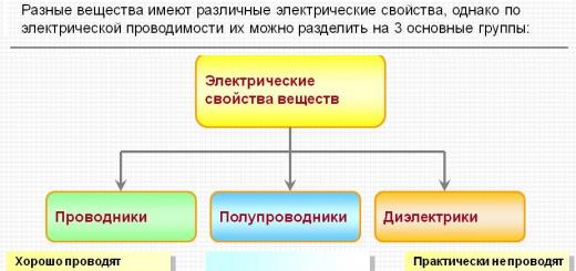
The value of the moment of inertia characterizes the resistance of the rod to deformation (torsion, bending) depending on the size and shape of the cross section. There are moments of inertia:
are axial, determined by integrals of the form
The axial and polar moments of inertia are always positive and do not
turn to zero. Polar moment of inertia Ip is equal to the sum of the axial moments of inertia I x and I y about any pair of mutually perpendicular axes X and at:
The centrifugal moment of inertia can be positive, negative or zero. The dimension of the moments of inertia is cm 4 or m 4. Formulas for determining the moments of inertia of simple sections about the central axes are given in reference books. When calculating the moments of inertia of complex sections, formulas for the transition from the central axes of simple sections to other axes parallel to the central ones are often used.
where are the moments of inertia of simple sections about the central axes;
m,n– distance between axes (Fig. 18).

Rice. 18. To determine the moments of inertia about the axes,
The main central axes of the section are important. The main central ones are two mutually perpendicular axes passing through the center of gravity of the section, relative to which the centrifugal moment of inertia is zero, and the axial moments of inertia have extreme values. Principal moments of inertia are denoted I u(max) and Iv(min) and are determined by the formula
The position of the principal axes is determined by the angle α, which is found from the formula
Angle α is plotted from an axis with a large non-principal moment of inertia; a positive value is counterclockwise.
If the section has an axis of symmetry, then this axis is the main one. The other main axis is perpendicular to the axis of symmetry. In practice, sections are often used, made up of several rolled profiles (I-beam, channel, corner). The geometric characteristics of these profiles are given in the assortment tables. For unequal and equilateral corners, the centrifugal moment of inertia about the central axes parallel to the shelves is determined by the formula
Pay attention to the designation of the main central axes in the assortment table for angles. Sign Ixy for a corner depends on its position in the section. Figure 19 shows the possible positions of the angle in the section and shows the signs for Ixy.
Rice. 19. Possible positions of the corner in the section
Define I u , I v and the position of the main central axes of the section
A complex section consists of two rolled profiles. An extract from the assortment tables (Appendix 5) is shown in fig. 21.
As auxiliary, we will take the axes passing along the outer
sides of the channel (axes x B, y B, see fig. 20).Coordinates of the center of gravity of the section:
(calculate yourself).

Rice. 20. Position of the main central axes of inertia
U and V complex section
As auxiliary one could choose, for example, the central axes of the channel. Then the amount of calculations will be somewhat reduced.
Axial moments of inertia:
Please note that the unequal corner in the section is located
other than shown in the grading table. Calculate the value yourself.

No. 24 180 x 110 x 12
Rice. 21. The values of the geometric characteristics of rolling profiles:
a- channel No. 24; b– unequal corner 180 x 110 x 12
Centrifugal moments of inertia:
- for the channel (there are axes of symmetry);
- for the corner
minus sign - due to the position of the corner in the section;
- for the entire section:
Follow the purpose of the signs n and m. From the central axes of the channel we pass to the common central axes of the section, therefore + m2
The main moments of inertia of the section:
The position of the main central axes of the section:
; α \u003d 55 about 48 ′;
Checking the correctness of the calculation of quantities I u, Iv and α is produced by the formula
The angle α for this formula is measured from the axis u.
The considered section has the greatest resistance to bending about the axis u and the smallest - relative to the axis v.
Chapter 5 d (see fig. 8.1): ...
Moments of inertia of sections
Properties of moments of inertia.Moments of inertia of plane sections
There are axial, polar and centrifugal moments of inertia of the sections. The axial moment of inertia of a section relative to any axis is the sum of the products of elementary products of areas d And pa the square of their distances to a given axis(see fig. 8.1): The polar moment of inertia of the section...(BUILDING MECHANICS FOR ARCHITECTS)
Static moments of plane sections
Rice. 2.24 When studying the issues of strength, stiffness and stability, it is necessary to be able to determine some geometric characteristics of sections, which include static moments, moments of inertia and moments of resistance. The static moment of the area of \u200b\u200bthe figure relative to the x-axis (Fig. 2.24), taken ...(APPLIED MECHANICS)
Moments of inertia of sections
The moments of inertia of the sections are integrals of the following form Properties of moments of inertia. The unit of moment of inertia is [length41, usually [m4] or [cm4|. Axial and polar moments of inertia are always positive. The centrifugal moment of inertia can be positive, negative or zero....(RESISTANCE OF MATERIALS USING COMPUTING COMPLEXES)
http//:www.svkspb.nm.ru
Geometric characteristics of flat sections
Square: , dF - elementary area.
Static moment of area elementdF about the 0x axis
 - product of the area element by the distance "y" from the 0x axis: dS x = ydF
Summing (integrating) such products over the entire area of the figure, we obtain static moments about the y and x axes: 
 ;
;
 [cm 3, m 3, etc.].
Center of gravity coordinates:
 . Static moments relative to central axes(axes passing through the center of gravity of the section) are equal to zero. When calculating the static moments of a complex figure, it is divided into simple parts, with known areas F i and coordinates of the centers of gravity x i, y i. The static moment of the area of the entire figure \u003d the sum of the static moments of each of its parts:
  .
.
The coordinates of the center of gravity of a complex figure: 
M
 moments of inertia of the section
Axial(equatorial) section moment of inertia- the sum of the products of elementary areas dF by the squares of their distances to the axis.
 ;
;
 [cm 4, m 4, etc.].
The polar moment of inertia of a section relative to a certain point (pole) is the sum of the products of elementary areas by the squares of their distances from this point.
 ; [cm 4, m 4, etc.]. J y + J x = J p .
Centrifugal moment of inertia of the section- the sum of the products of elementary areas by their distances from two mutually perpendicular axes.  .
.
The centrifugal moment of inertia of the section about the axes, one or both of which coincide with the axes of symmetry, is equal to zero.
Axial and polar moments of inertia are always positive, centrifugal moments of inertia can be positive, negative or zero.
The moment of inertia of a complex figure is equal to the sum of the moments of inertia of its constituent parts.
Moments of inertia of sections of a simple form
P 
 rectangular section Circle
To 


 ring
ring
T 
 rectangle
R  autofemoral
Rectangular
t 
 rectangle
H  quarter circle
J y \u003d J x \u003d 0.055R 4
Jxy =0.0165R 4
in fig. (-)
Semicircle
M 
 the moments of inertia of standard profiles are found from the assortment tables:
D 
 vutaur
Channel
corner
vutaur
Channel
corner
M

J  x1 = J x + a 2 F;
J y1 = J y + b 2 F;
the moment of inertia about any axis is equal to the moment of inertia about the central axis parallel to the given one, plus the product of the area of \u200b\u200bthe figure and the square of the distance between the axes. J y1x1 = J yx + abF; ("a" and "b" are substituted into the formula, taking into account their sign).
Relationship between moments of inertia when turning the axes:
J  x1 \u003d J x cos 2 + J y sin 2 - J xy sin2; J y1 \u003d J y cos 2 + J x sin 2 + J xy sin2;
J x1y1 =(J x - J y)sin2 + J xy cos2 ;
Angle >0, if the transition from the old coordinate system to the new one occurs counterclockwise. J y1 + J x1 = J y + J x
Extreme (maximum and minimum) values of moments of inertia are called main moments of inertia. The axes with respect to which the axial moments of inertia have extreme values are called main axes of inertia. The principal axes of inertia are mutually perpendicular. Centrifugal moments of inertia about the main axes = 0, i.e. principal axes of inertia - axes with respect to which the centrifugal moment of inertia = 0. If one of the axes coincides or both coincide with the axis of symmetry, then they are principal. Angle defining the position of the main axes:  , if 0 >0 the axes are rotated counterclockwise. The axis of maximum always makes a smaller angle with that of the axes, relative to which the moment of inertia has a greater value. Principal axes passing through the center of gravity are called main central axes of inertia. Moments of inertia about these axes:
J max + J min = J x + J y . The centrifugal moment of inertia about the main central axes of inertia is 0. If the main moments of inertia are known, then the formulas for the transition to rotated axes are:
J x1 \u003d J max cos 2 + J min sin 2 ; J y1 \u003d J max cos 2 + J min sin 2 ; J x1y1 =(J max - J min) sin2;
The ultimate goal of calculating the geometric characteristics of the section is to determine the main central moments of inertia and the position of the main central axes of inertia. R  radius of inertia -
 ; J x =Fi x 2 , J y =Fi y 2 .
If J x and J y are the main moments of inertia, then i x and i y - principal radii of gyration. An ellipse built on the main radii of inertia as on semiaxes is called ellipse of inertia. Using the ellipse of inertia, you can graphically find the radius of gyration i x1 for any x 1 axis. To do this, draw a tangent to the ellipse parallel to the x 1 axis, and measure the distance from this axis to the tangent. Knowing the radius of gyration, you can find the moment of inertia of the section about the x-axis 1:  . For sections with more than two axes of symmetry (for example: a circle, a square, a ring, etc.), the axial moments of inertia about all central axes are equal to each other, J xy \u003d 0, the ellipse of inertia turns into a circle of inertia.
moments of resistance.
Axial moment of resistance- the ratio of the moment of inertia about the axis to the distance from it to the most distant point of the section.  [cm 3, m 3]
Particularly important are the moments of resistance relative to the main central axes:
rectangle:  ; circle: Wx=Wy=
  ,
,
tubular section (ring): W x =W y =  , where = d H /d B .
Polar moment of resistance - the ratio of the polar moment of inertia to the distance from the pole to the most distant point of the section:  .
.
For circle W p =  .
.
There are the following types of moments of inertia of sections: axial; centrifugal; polar; central and principal moments of inertia.
Centrifugal moments of inertia section relative at and z called the integral of the form The sum of the axial moments of inertia of the section about two coordinate axes is equal to the polar moment of inertia about the origin:The dimension of the specified types of moments of inertia of the section (length 4), i.e. m 4 or cm 4.
Axial and polar moments of inertia of the section are positive values; the centrifugal moment of inertia can be positive, negative and equal to zero (for some axes that are the axis of symmetry).
There are dependencies for the moments of inertia for parallel translation and rotation of the coordinate axes.
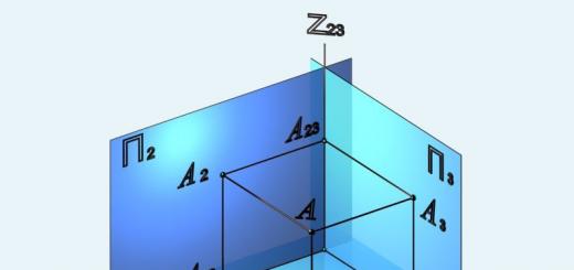
 Figure 5.4 - Parallel translation and rotation of the coordinate axes for an arbitrary cross section of the beam
If the moments of inertia of the section are known Iz, Iy, Izy about the axes z and at, then the moments of inertia about the rotated axes z1 and 1, at an angle α with respect to the original axes (Fig. 5.4, b) is determined by the formulas:

With a concept principal moments of inertia relate the position of the principal axes of inertia. Principal axes of inertia two mutually perpendicular axes are called, with respect to which the centrifugal moment of inertia is zero, and the axial moments acquire extreme values (maximum and minimum).
If the main axes pass through the center of gravity of the figure, then they are called main central axes of inertia.
The position of the main axes of inertia is found from the following dependencies:In calculating the strength of structural elements, the concept of such a geometric characteristic as section modulus.
Consider, for example, the cross section of a beam (Fig. 5.5).

Figure 5.5 - An example of a cross-section of a beam
The distance of the most remote BUT from the center of gravity of the section C o designate h1, and the distance t. AT- through h2.
| (5.16) |
Of practical interest in strength calculations is the smallest section modulus wmin, corresponding to the most distant t. BUT from the center of gravity of the section h 1 = y max.
The dimension of the resistance elements (length 3), i.e. m 3, cm 3.
Table 5.1 - Values of the moments of inertia and moments of resistance of the simplest sections relative to the central axes
| Section name types | Moments of inertia | Moments of resistance | ||
| Rectangle |  | |||
| A circle |  | |
continuation of table 5.1
Axial (or equatorial) moment of inertia of the section about some axis is called taken over its entire area F dF by the squares of their distances from this axis, i.e.
The polar moment of inertia of a section with respect to a certain point (pole) is taken over its entire area F sum of products of elementary areas dF by the squares of their distances from this point, i.e.
The centrifugal moment of inertia of a section with respect to some two mutually perpendicular axes is called taken over its entire area F sum of products of elementary areas dF at their distances from these axes, i.e.
The moments of inertia are expressed in cm 4, m 4, etc. The axial and polar moments of inertia are always positive, since their expressions under the signs of the integrals include the values of the areas dF(always positive) and the squares of the distances of these sites from the given axis or pole.
Figure 2.3 shows a cross section with an area F and showing axes at and x.
Rice. 2.3. Section area F.
Axial moments of inertia of this section relative to the axes at and x:
The sum of these moments of inertia
hence,
The sum of the axial moments of inertia of a section about two mutually perpendicular axes is equal to the polar moment of inertia of this section about the point of intersection of these axes.
The centrifugal moments of inertia can be positive or zero. The centrifugal moment of inertia of a section about axes, one or both of which coincide with its axes of symmetry, is equal to zero. The axial moment of inertia of a complex section about a certain axis is equal to the sum of the axial moments of inertia of its constituent parts about the same axis. Similarly, the centrifugal moment of inertia of a complex section about any two mutually perpendicular axes is equal to the sum of the centrifugal moments of inertia of its constituent parts about the same axes. Also, the polar moment of inertia of a complex section relative to a certain point is equal to the sum of the polar moments of inertia of its constituent parts relative to the same point. It should be borne in mind that the moments of inertia calculated with respect to different axes and points cannot be summed.
For rectangle
For a circle
For the ring
Often, when solving practical problems, it is necessary to determine the moments of inertia of a section relative to axes oriented in different ways in its plane. In this case, it is convenient to use the already known values of the moments of inertia of the entire section (or individual parts of it) relative to other axes, given in the technical literature, special reference books and tables, as well as calculated using the available formulas. Therefore, it is very important to establish the relationship between the moments of inertia of the same section relative to different axes.
In the most general case, the transition from any old to any new coordinate system can be considered as two successive transformations of the old coordinate system:
1) by parallel transfer of the coordinate axes to a new position;
2) by rotating them relative to the new origin.
Hence,
If the axis X passes through the center of gravity of the section, then the static moment S x= 0 and
Of all the moments of inertia about parallel axes, the axial moment of inertia has the smallest value about the axis passing through the center of gravity of the section.
Moment of inertia about the axis at
In the particular case when the axis / passes through the center of gravity of the section,
centrifugal moment of inertia
In a particular case, when the origin of the old coordinate system y0x located in the center of gravity of the section,
If the section is symmetrical and one of the old axes (or both) coincides with the axis of symmetry, then