Calculation of bars in eccentric compression-tension
Example 1
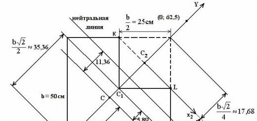
Cast iron short the rod is compressed by a longitudinal force F= 600 kN applied at the point IN.
Required:
1. Determine the position of the neutral line;
2. Calculate the greatest tensile and greatest compressive stresses.
Solution.

1. Draw the section to scale.
2. Determine the position of the main central axes. The section has an axis of symmetry, so the axis Y we can show you right now.
3. Determine the position of the center of gravity of the figure (the figure consists of two squares). We choose an arbitrary auxiliary coordinate system.
x 1 C 1 Y– auxiliary coordinate system;
determine the coordinates of the points FROM 1 and FROM 2 in the system x 1 C 1 Y.
![]()
BUT 1 , BUT 2 is the area of the first and second square, respectively.
A \u003d A 1 - A 2 is the area of the whole figure.
BUT 1 = b 2 \u003d 2500 cm 2
![]()
![]()
FROM (X c = 0; at c = -5.89) - the position of the center of gravity in the auxiliary coordinate system x 1 C 1 Y.
Axis X draw perpendicular to the axis Y through a point FROM.
Since the section is symmetrical, then XC Y is the main central coordinate system.
4. Determine the main central moments of inertia and the squares of the main radii of the section.

where but 1 \u003d 5.89 cm - distance between the axles X And X 1 ;
but 2 \u003d 5.89 + 17.68 \u003d 23.57 - distance between the axles X And X 2 .
![]()
![]()
5. Determine the coordinates of the point IN(points of application of force) in the main central coordinate system x with Su with.

6. Determine the position of the neutral line.
![]() ,
,
where X N, at N - coordinates of the points of the neutral line.
In this task
![]()
![]()
![]()
The neutral line passes through the point ( X N=0;at N = 11.36) parallel to the axis X from.
7. In this problem, a compressive force acts on the rod, so the normal stresses at any point of the cross section will be determined by the formula

where x, y are the coordinates of the point at which the stresses are calculated.
8. The greatest compressive stresses are achieved at the point IN. This is the point furthest from the neutral line in the compression region.
The greatest tensile stresses are achieved at the points TO And Ly K = at L = 23.57 cm.
Answer:
![]() ,
, ![]()
Example 2
Construct a section kernel.

Solution.
1. Determine the type of contour of the section core.
2. We determine the number of vertices of the polygon obtained inside the contour (that is, the number of limit tangents to the section of the rod). 6 limit tangents - 6 vertices.
3. Determine the position of the main central axes. The section has a horizontal axis of symmetry, so the axis " X We can show right away. XOY 0 - auxiliary coordinate system (axis " Y 0 "we spend arbitrarily).
The section consists of two simple shapes (rectangle and square). Determine the coordinates of the centers of gravity FROM 1 and FROM 2 in an arbitrary coordinate system XOY 0 .
The center of gravity of the rectangle.
The center of gravity of the square.
The area of the rectangle.
Square area.
![]() (because FROM 1 and FROM 2 lie on the axis).
(because FROM 1 and FROM 2 lie on the axis).
The center of gravity of the entire section in the coordinate system XOY 0 has coordinates FROM(0.015; 0). (We will show in the drawing).
Axis Y draw perpendicular to the axis Y 0 through the center of gravity FROM.
Since the section is symmetrical, the axis of symmetry and the axis perpendicular to it, passing through the center of gravity, form the main central coordinate system.
X, Y are the main central axes of the section.
4. We determine the geometric characteristics of the section relative to the main central axes.
We calculate the main central moments of inertia J x and J y .
Principal central moments of inertia of a rectangle.
Principal central moments of inertia of a square.

(Here formulas were used to determine the moments of inertia about parallel axes. Axial moments of inertia of a plane section about arbitrary axes X 1 and at 1 parallel to the central axes X And at, determined by the formulas
![]()
![]() ;
;
where but,b– distance between axles X And X 1 , at And at 1 , BUT- cross-sectional area. it is accepted that x, y– central axes, i.e. axes passing through the center of gravity FROM flat section).

Calculate the squares of the main radii of inertia
![]()
5. Determine the vertices of the core of the section.
Let the position of the neutral line be known. It is required to determine the coordinates of the force application point.
1. Consider the position of the neutral line 1 - 1.
![]()
Use the property of the neutral line. Since the neutral line 1-1 runs parallel to the axis Y, then the point of application of the force I 1 is on the axis X, i.e at F=0.

X N - abscissa of the point of the neutral line 1 - 1 (distance from the point FROM to the neutral line 1 - 1).
2. Consider the position of the neutral line 2 - 2.
![]()
Take two points of the neutral line 2 - 2 (it is better to choose points where you can easily calculate the coordinates)
IN(-0.615; 0.3) and D(-0,015; 0,6)
Substitute the coordinates of the points IN And D into the neutral line equation.
![]() (1)
(1)
![]() (2)
(2)
Let's solve the system of equations (1) - (2)

From the first equation
![]()
![]() (3)
(3)
Substitute (3) into (2)
![]()
![]()
3. Consider the position of the neutral line 3 - 3.
![]()
Use the property of the neutral line. Since the neutral line 3 - 3 runs parallel to the axis X, then the point of application of the force I 3 is on the axis Y, i.e X F =0.
![]()
at N - ordinate of the point of the neutral line 3 - 3 (distance from the point FROM to the neutral line 3 - 3).
4. Consider the position of the neutral line 4 - 4.
![]()
Use the property of the neutral line. Since the neutral line 4 - 4 runs parallel to the axis Y, then the point of application of the force I 4 is on the axis X, i.e at F = 0.

Example3 .
A rigid rod is loaded with two forces - tensile and compressive (Fig. 1). The rod is made of a brittle material with characteristics and . The cross section of the rod is symmetrical and has the shape and dimensions corresponding to Fig. 2.
Required:
1) find the allowable load on the rod from the strength condition, if the ratio of compressive and tensile forces
2) build the core of the section.


Fig.1Fig.2
Solution.
The position of the main central axes of inertia and the moments of inertia about these axes of a given section were found earlier (see the section "Geometric characteristics of flat sections"). Let's find the internal forces in an arbitrary section of the rod:
![]()
![]()
To determine the position of dangerous points, we construct a neutral line. Neutral line equation  in this problem has the form
![]()
From here we find the segments cut off by the neutral line on the axes and . If , then
![]()
and if , then
![]()
The neutral line is shown in fig. 3.

Fig.3
Draw tangents to the contour of the section, parallel to the neutral line. Points 1 and 1 are dangerous ¢
(see Fig. 3), the most distant from the neutral line. For a brittle material, the point with maximum tensile stresses is more dangerous, i.e. point 1. Find the voltage at this point by substituting into the formula  point 1 coordinates:
Strength condition at point 1 Or
![]()
From here you can find the allowable load value (do not forget to substitute the units of measurement correctly. Multiplier before F p in this example has the dimension cm -2).
In conclusion, it is necessary to make sure that at point 1 ¢ , which in this example is further removed from the neutral axis than point 1, and in which compressive stresses act, the strength condition is also satisfied, i.e.
![]()
Now let's build the kernel of the section. We place the poles at the outer corner points of the section. Given the symmetry of the section, it is sufficient to place the poles at three points: 1, 2 and 3 (see Fig. 3). Substituting into formulas ; the coordinates of the poles, we find the segments cut off by neutral lines on the axes and . If the pole is at point 1, then its coordinates ![]() And
And
![]()
![]()
The neutral line 1–1 corresponding to the pole at point 1 is shown in fig. 3. Similarly, we build neutral lines 2–2 and 3–3, corresponding to poles 2 and 3. When constructing a neutral line, make sure that it runs in the opposite quadrant to that in which the pole is located. The area shaded in Fig. 3 is the core of the section. For control in Fig. 3 shows the ellipse of inertia. The core of the section must be inside the ellipse of inertia, without crossing it anywhere.
Example 4
A rod of an asymmetric section is compressed by a force applied at a point BUT (Fig. 1). The cross section has the shape and dimensions shown in fig. 2. The material of the rod is brittle.
Required:
1) find the allowable load that satisfies the strength condition;
2) build the core of the section.
Solution.
First of all, it is necessary to determine the moments and radii of inertia of the cross section relative to the main central axes. This part of the solution of the problem is given in the section "Geometric characteristics of flat sections". On fig. 1 shows the main central axes of inertia of the section , , whose position was found earlier. In the system of central axes Y ,Z(Fig. 2) coordinates of the force application point BUT , . Calculate the coordinates of the point BUT in the system of main central axes according to the formulas
![]() .
.


Fig.1Fig.2
To determine the position of dangerous points, we will construct a neutral line using the formulas ; . Radii of inertia, found earlier.
![]()
![]()
Let us lay these segments along the main axes and draw a neutral line through the obtained points (see Fig. 3).

Fig.3
Dangerous points, i.e. the points farthest from the neutral axis will be points 1 and 3 (see Fig. 3). At point 1, the greatest tensile stress acts. We write the strength condition at this point using the formula ![]() :
:

Let us substitute the coordinates of dangerous point 1 in the main axes into the strength condition, calculating them using the formulas
or by measuring on a drawing drawn to scale, ![]()
![]() Then, from the strength condition at point 1, you can find the allowable load value:
Then, from the strength condition at point 1, you can find the allowable load value:
 .
.
For the found value of the allowable load, it is necessary to make sure that the strength condition is also fulfilled at point 3, which is further removed from the neutral line and in which the compressive stress acts. To determine the voltage at point 3, we substitute the coordinates of this point into the formula

 .
.
This voltage should not exceed . If the strength condition at the point with maximum compressive stresses is not met, it is necessary to find the value of the allowable load again from the strength condition at this point.
In conclusion, we construct the kernel of the section. We place the poles at the outer corner points of the section, i.e. at points 1, 2, 3, 4, 5 (see Fig. 3). Point 4, located on the contour of the quadrant of the circle, was obtained as follows. Cutting off the inner corner point , we draw a line tangent to the section contour (dotted line in Fig. 3). Point 4 is the point where this line touches the quadrant of the circle. We sequentially find the position of the neutral lines corresponding to the poles at the indicated points, finding the segments cut off by the neutral lines on the axes , , according to the formulas ; .For example, if the pole is at point 1, then substituting into ; coordinates of point 1 (), find
![]()
![]()
Since it is much larger, this means that the neutral line 1–1 is practically parallel to the axis. We plot the segment on a scale along the axis and draw a straight line 1–1 parallel to the axis (see Fig. 3). Similarly, we build neutral lines corresponding to the poles located at other points. The core of the section (shaded area) is shown in fig. 3. Note that the contour of the core of the section between the neutral lines 4–4 and 5–5 is outlined along a curve, since the transition of the pole from point 4 to point 5 does not occur in a straight line. On fig. 3 also shows the ellipse of inertia of the section, built earlier.
Example 5
On a beam of a given cross section at a point D the upper end there is a longitudinal compressive force R=300 kN (see figure). It is required to find the position of the zero line, determine the largest (tensile and compressive) stresses and construct the core of the section.
Solution:
1. Finding the position of the main central axes of inertia and determining the cross-sectional area
Since the cross section of the beam (Fig. 1) has two axes of symmetry, and they always pass through the center of gravity of the section and are the main ones, then the main central axes of the section X with and at c will coincide with these axes of symmetry.

Center of gravity of the section FROM in this case, it is not necessary to determine, since it coincides with the geometric center of the section.
The cross-sectional area of \u200b\u200bthe beam is equal to:
2. Determination of the main central moments of inertia and the main radii of inertia
The moments of inertia are determined by the formulas:


We calculate the squares of the main radii of inertia:

3. Determining the position of the zero line
The segments cut off by the zero line on the main central axes of inertia are determined by the formulas:


where x p=2.3 cm and y r\u003d 2 cm - coordinates of the point of application of force R(point P Fig.11). Putting aside the segments and respectively on the axes x s And u s and drawing a straight line through their ends, we obtain a zero section line, on which the normal stresses are equal to zero (). In Figure 1, this line is marked n -n.
4. Determination of the highest compressive and tensile stresses and construction of a stress diagram
Point D , whose coordinates X D =5.25 cm and at D\u003d 5 cm, the most distant from the zero line in the compressed zone of the section, therefore, the largest compressive stresses occur in it and are determined by the formula
The greatest tensile stresses occur at point K, which has coordinates x k= -5.25 cm, at k= -5 cm.
Based on the obtained values and we build a diagram of normal stresses (see Fig. 11).
5. Construction of the section kernel
To construct the core of the section, given that the section is symmetrical, consider two positions of the tangent to the contour of the section I-I and II-II (see fig. 1).
Segments cut off by the tangent I -I
on the coordinate axes are equal to: ![]()
The coordinates of the boundary point 1 of the core of the section are determined by the formulas:


Tangent II-II cuts off segments = 5.25 cm, = ¥ .
Boundary Point Coordinates 2 :


The coordinates of the boundary points of the second half of the core of the section may not be determined, since the section of the beam is symmetrical. Taking this into account for the tangents III -III and IV -IV, the coordinates of the boundary points 3 And 4 will be:
= 0; = 15,2× 10 -3 m;
=23,0× 10 -3 m = 0.
Connecting points 1, 2, 3 and 4 in series with straight lines, we get the core of the section (Fig. 1).
Example 6
In the section indicated in the figure and belonging to an eccentrically compressed column, determine the most dangerous points and the stresses in them. Compressive force F= 200 kN = 20 t applied at point A.

Solution.
Since the X and Y axes are the axes of symmetry, they are the main central axes.
The most dangerous points will be the points at which maximum normal voltage, and these are the points furthest from the zero line. Therefore, we need to first determine the position of the zero line. We write the equation of the zero line.
In our case, the coordinates of the force application point are as follows (see Fig.):
= - 90 mm = - 0.09 m;
= - 60 mm = - 0.06 m.
The squares of the radii of inertia and are defined as follows:
here and - axial moments of inertia about the main central axes X and Y.
Determination of axial moments of inertia. For our section we will have:
M 4 ;
M 4 .
The area of the entire section will be equal to:
M 2,
and then the squares of the radii of inertia:
![]() m 2;
m 2;
![]() m 2.
m 2.
Using the formulas, we determine the segments that the zero line cuts off on the axes X And Y:
![]() m;
m;
![]() m.
m.
Let's set aside these segments on the coordinate axes, we get the points at which the zero line crosses the coordinate axes. We draw a straight line through these points (see Fig.). We see that the most distant points - this is point B in the zone of negative stresses and point D in the zone of positive stresses.
Let's determine the stresses at these points:
![]() ;
;
Based on the drawing (see Fig.) we get:
= - 0.12 m; = - 0.03 m.
= –5,39× 10 4 kN / m 2 \u003d - 53.9 MPa.
![]() ;
;
0.12 m; = 0.03 m.
1,86× 10 4 kN / m 2 \u003d 18.6 MPa.
Example 7
Cast iron shorta rod whose cross section is shown in the figure is compressed by a longitudinal force F, applied at the point BUT.
Required:
1) calculate the largest tensile and largest compressive stresses in the cross section, expressing the magnitude of these stresses through F and section dimensions; but= 40 mm, b= 60 mm;
2) find the allowable load F at given cross-sectional dimensions and allowable stresses for cast iron for compression = 100 MPa and for tension = 30 MPa.

Solution.
It was mentioned above that the geometric characteristics in the calculation formulas are taken relative to the main central axes, so we will determine the center of gravity of the section. Axis X is an axis of symmetry, and therefore, it passes through the center of gravity, so we just need to find its location on this axis. Let's divide the section into two components (1 and 2) and select auxiliary axes. FROM 1 and FROM 2 in these axes.
Will have FROM 1 (0,0); FROM 2 (0.04; 0), then:
m;
So in axes xy 1 the center of gravity of the entire section has coordinates FROM (0.0133; 0). We draw an axis through the center of gravity of the section Y perpendicular to the axis X. X axis and Y and will be the main central axes of the section.
Let's determine the position of the zero line.
Force application point coordinates (points BUT) will be as follows: \u003d (0.02–0.0133) + 0.04 \u003d 0.0467 m; = 0.06 m;
m 4,
m 4,
where = 0.0133 m;
m 2.
![]() m 2,
m 2, ![]() m 2;
m 2;
and get the segments cut off by the neutral axis on the main axes of inertia X and Y, respectively:
![]()
Set aside on the axis X, and on the axis Y and draw a zero line through the obtained points (see Fig.). We see that the most distant points of the section from the zero line - this is the point BUT in the compressed zone and point IN in the extended zone. The coordinates of these points are as follows: BUT(0,0467; 0,06); IN(-0.0333; -0.12). Let us determine the stresses at these points, expressing them in terms of F.
Point voltage BUT must not exceed the allowable compressive stress , and the voltage at the point IN must not exceed the allowable tensile stress, i.e. conditions must be met:
, ,
or
(but),
(b).
From (a): ![]()
from (b): ![]()
In order to simultaneously satisfy the strength condition in both the stretched and compressed zones of the column, we must take the smaller of the two received as the allowable load, i.e. = 103 kN.
Example 8
Cast iron short a rod of rectangular cross section, shown in the figure, is compressed by a longitudinal force F, applied at the point BUT.
Required:
1) calculate the largest tensile and largest compressive stresses in the cross section, expressing the magnitude of these stresses through F and section dimensions;
2) find the allowable load F at given cross-sectional dimensions and allowable stresses for cast iron in compression ![]() and tensile
and tensile ![]() .
.

Solution.
Let's determine the position of the zero line. To do this, we use the formulas
The coordinates of the force application point (point A) will be as follows:
![]()
![]()
The squares of the radii of inertia are determined by the formulas:

Determine the segments that the zero line cuts off on the axes X And at.

Set aside on the axis X – X 0 , and on the axis at – at 0 and draw a zero line through the obtained points n – n(see fig.). We see that the most distant points of the section are point A in the compressed area and point B in the stretched area. The coordinates of these points are as follows: A (0.04; 0.06), B (–0.04; –0.06). Let us determine the magnitude of the stress at these points, expressing them in terms of the force F:
The stress at point A should not exceed the allowable compressive stress, and the stress at point B should not exceed the allowable tensile stress, i.e. the condition must be met
From the first expression, the value F
![]()
![]()
The load is the smallest of the two found, i.e. = 567kn.
Example 9
A short cast iron rod with the cross section shown in fig. but, is compressed by a longitudinal force P, applied at the point A. Determine the greatest tensile and greatest compressive stresses in the cross section of the rod, expressing them in terms of force P and cross-sectional dimensions, cm, cm. Find the allowable load at given allowable stresses for the material for compression kN / cm 2 and for tension kN / cm 2.

Solution.
Force acting on the rod P in addition to compression, it bends the rod relative to the main central axes x And y. The bending moments are respectively equal:
where cm and cm are the coordinates of the force application point P(point coordinates A).
Normal stresses at some point with coordinates x And yany cross section of the rod are determined by the formula
 ,
,
where F is the area, and and are the radii of gyration of the cross section.
1. Determine the geometric characteristics of the cross section of the rod.
The cross-sectional area of the rod is:
The main central moments of inertia are determined as follows.
Calculating moment of inertia Total section about the axis x, split the whole figure into one rectangle with width and height and two rectangles with width and height so that the axis x was central to all these three figures. Then
![]() .
.
To calculate the moment of inertia of the entire section about the axis y let's split the whole figure a little differently: one rectangle with width and height and two rectangles with width and height so that now the axis y was central to all these three figures. Get
![]() .
.
The squares of the radii of inertia are:
![]() ;
; ![]() .
.
2. Determine the position of the zero line.
The segments and , cut off by the zero line from the coordinate axes, are equal to:
 cm ;
cm ;  cm.
cm.
Show zero line N-N in fig. b. The zero line divides the cross section into two regions, one of which is in tension and the other is in compression. Figure 1, b stretched cross-sectional area of the rod by us shaded.
3. Calculate the largest stretching voltage.
It occurs at the points 6 And 7 , that is, at the points furthest from the zero line. The value of this voltage, calculated, for example, for a point 6 equals:
4. Calculate the largest compressive voltage.
It occurs at the points 2 And 3 , also the furthest from the zero line. The value of this voltage, calculated, for example, for a point 2 , equals:
5. Determine the allowable load from the condition of tensile strength:
![]() kN/cm 2 ;
kN/cm 2 ; ![]() kN.
kN.
6. Determine the allowable load from the condition of compressive strength:
![]() kN/cm 2 ;
kN/cm 2 ; ![]() kN.
kN.
Example 10
A short column, the cross section of which is shown in Fig. 1, is compressed by a longitudinal force F= 200 kN applied at the point TO. Section dimensions a= 40 cm b= 16 cm Estimated tensile strength of the material R t = 3 MPa, for compression R with = 30 MPa .
Required:
1. Find the position of the zero line.
2. Calculate the greatest compressive and tensile stresses and build a stress diagram. Give a conclusion about the strength of the column.
3. Determine the design bearing capacity (design load) F max for given section sizes.
4. Construct the core of the section.

Fig.1
Solution.
1. Determining the coordinates of the center of gravity of the section.
The cross section of the column has an axis of symmetry X s, therefore, the center of gravity lies on this axis and to find the coordinate x s relative to the minor axis Y o (see Fig. 1) we divide the complex section into three rectangles
2. Geometric characteristics of the section.
To calculate the main central moments of inertia, we use the relationship between the moments of inertia with parallel translation of the axes.
Determine the squares of the radii of inertia
![]()
![]()
force application point coordinates F
3. Zero line position


Found segments cut off on the coordinate axes we draw zero line (see Fig. 2).
4. Determination of the highest compressive and tensile stresses. Diagram .
The points farthest from the zero line: IN(-60; 16)AndD(60; -32). Stresses at these dangerous points with coordinates X Dan , y Dan must not exceed the corresponding design resistance
 .
.
Tensile stress
Compressive stress
The strength of the column is guaranteed.
According to the results of stress calculation and in fig. 2 built diagram .
5. Calculation of the calculated bearing capacity of the column Fmax .
Since, at a given value of the compressive force, the strength of the column material is significantly underutilized, we find the maximum value of the external load by equating the maximum stresses s t And s c calculated resistance.


Finally choose a smaller value Fmax = 425.8 kN, providing strength to both stretched and compressed cross-sectional zones.

Fig.2
6. Construction of the section kernel.
To obtain the outline of the core of the section, it is necessary to consider all possible positions of the tangents to the contour of the section and, assuming that these tangents are zero lines, calculate the coordinates of the boundary points of the core relative to the main central axes of the section. Then connecting these points, we obtain the outline of the core of the section.
Tangent 1-1: y o = 32 cm,
![]() .
.
Tangent 2-2: ,  .
.
Tangent 3-3: , ![]() .
.
Tangent 4-4: ![]() ; ;
; ;
![]() ;
;
;
;
![]() ;
;
![]() .
.
Tangent 5-5: ; ![]() .
.
Tangent 6-6: ; ![]() ;
;
Example 11 .
At the point P Rectangular column compressive force applied P(see fig.). Determine the maximum and minimum normal stresses.

Solution.
The normal stress under eccentric compression is determined by the formula:

In our task ![]()
Moment of inertia, area ![]() ,
,
Consequently 
On the neutral line. So her equation
![]()
The points farthest from the neutral axis are the points A And B:
at the point A And
![]()
at the point B And
![]()
If the material resists tension and compression differently, then two strength equations should be drawn up:

Example 12.
Find the allowable load for the beam shown in the figure, if the design resistances of the beam material for tension and compression are equal Radm ,t= 20 MPa; R adm , with= 100 MPa.

Solution. We write the strength condition for the most stressed points of any section of the beam, since all sections are equally dangerous:
![]()
![]()
Let us rewrite these conditions, taking into account that
and then
![]() And
And 
From here we determine the values of permissible loads.
Eccentric tension (compression) is caused by a force parallel to the beam axis, but not coinciding with it (Fig. 9.4).
The projection of the point of application of force on the cross section is called the pole or power point, and the straight line passing through the pole and the center of the section is called the line of force.
Eccentric tension (compression) can be reduced to axial tension (compression) and oblique bending if the force P is transferred to the center of gravity of the section. So, the force P, marked in Fig. 9.4 with one dash G will cause axial tension of the beam, and a pair of forces marked with two dashes will cause an oblique bend.
Based on the principle of independence of the action of stress forces at the points of the cross section during eccentric tension (compression), they are determined by the formula
In this formula, the axial force, bending moments, as well as the coordinates of the section point at which the stress is determined, must be substituted with their signs. For bending moments, we will take the same sign rule as in oblique bending, and we will consider the axial force positive when it causes tension.
If the coordinates of the pole are denoted by , then the moment Formula (9.5) takes the form
![]()
It can be seen from this equation that the ends of the stress vectors at the points of the section are located on the plane. The line of intersection of the stress plane with the plane of the cross section is a neutral line, the equation of which is found by equating the right side of equality (9.6) to zero. After reduction by P we get
![]()
![]()
Thus, the neutral line in off-center tension (compression) does not pass through the center of gravity of the section and is not perpendicular to the plane of action of the bending moment. The neutral line cuts off segments on the coordinate axes
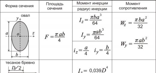
We represent the moments of inertia as the product of the cross-sectional area and the square of the corresponding radius of inertia
Then expressions (9.8) can be written as follows:
![]()
From formulas (9.8) it can be seen that the pole and the neutral line are always located on opposite sides of the center of gravity of the section, and the position of the neutral line is determined by the coordinates of the pole.


When the pole approaches the center of gravity of the section along the line of force, the neutral line will move away from the center, remaining parallel to its original direction. In the limit at , the neutral line recedes to infinity. In this case, there will be a central tension (compression) of the beam.
On the line of force, you can always find such a position of the pole, in which the neutral line will touch the contour of the section, without crossing it anywhere. If we draw all possible neutral lines so that they touch the contour of the section, without crossing it anywhere, and find the poles corresponding to them, then it turns out that the poles will be located on a closed line that is quite specific for each section. The area bounded by this line is called the core of the section. In a circular section, for example, the core is a circle with a diameter 4 times smaller than the diameter of the section, and in rectangular and I-sections, the core has the shape of a parallelogram (Fig. 9.5).
It follows from the very construction of the core of the section that as long as the pole is inside the core, the neutral line will not cross the contour of the section and the stresses in the entire section will be of the same sign. If, however, the pole is located outside the core, then the neutral line will cross the contour of the section, and then stresses of different signs will act in the section. This circumstance must be taken into account when calculating off-center compression of racks made of brittle materials. Since brittle materials poorly perceive tensile loads, it is desirable to apply external forces to the rack so that only compressive stresses act in the entire section. To do this, the point of application of the resultant of external forces compressing the rack must be inside the core of the section.
The calculation for strength in off-center tension and compression is carried out in the same way as in oblique bending - according to the stress at the dangerous point of the cross section. Dangerous is the point of the section, the most distant from its neutral line. However, in cases where compressive stress acts at this point, and the strut material is brittle, the point where the greatest tensile stress acts may be dangerous.
The stress diagram is built on an axis perpendicular to the neutral line of the section, and is limited by a straight line (see Fig. 9.4).
The strength condition is written as follows.
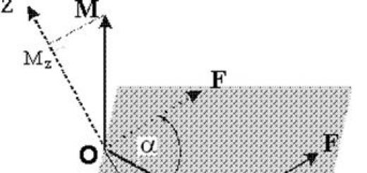
Consider a straight rod loaded at the end with forces directed parallel to the axis Oh. The resultant of these forces F applied at the point FROM. In the local right-handed coordinate system yOz, coinciding with the main central axes of the section, the coordinates of the point FROM equal but And b(Fig. 5.18).
Let us replace the applied load with a statically equivalent system of forces and moments. To do this, we transfer the resultant force F to the center of gravity of the section ABOUT and load the rod with two bending moments equal to the product of the force T^ on its arms with respect to the coordinate axes: M ff = Fa And Mz = Fb.
Note that according to the rule of the right-handed coordinate system for the point C, which lies in the first quadrant, the bending moments will formally receive the following
Rice. 5.18.Straight rod loaded at the end with forces directed parallel to the axisOh
blowing signs: M y \u003d Fa and M 7 = -Fb. In this case, in the elementary area lying in the first quarter, both moments cause tensile stress.
Using the principle of independence of the action of forces, we determine the stresses at the current point of the section with coordinates at And z from each power factor separately. The total voltage is obtained by summing all three voltage components:
Let us determine the position of the neutral axis. To do this, in accordance with formula (5.69), we equate to zero the value of the normal stress at the current point:

As a result of simple transformations, we obtain the neutral line equation
where i y And i z - main radii of inertia determined by formulas (3.14).
Thus, in the case of eccentric tension-compression, the neutral line does not pass through the center of gravity of the section (Fig. 5.19), as indicated by the presence in equation (5.70) of a free term that differs from zero.
The maximum stresses occur at the points of the section BUT And IN, farthest from the neutral line. Let's establish the relationship between the coordinates of the force application point and the position of the neutral line. To do this, we determine the points of intersection of the coordinate axes by this line:

Rice. 5.19.
The resulting formulas show that the coordinate of the force application point but and the coordinate of the point of intersection of the neutral line of the coordinate axis Oz(point r 0) have opposite signs. The same can be said about the quantities b And at 0 . Thus, the point of application of the resultant force and the neutral line are on opposite sides of the origin.
According to the obtained formulas, when the point of force application approaches the center of gravity of the section, the neutral line moves away from the central zone. In the limiting case (a = b = 0) we arrive at the case of central tension-compression.
It is of interest to determine the zone of force application, in which the stresses in the section will have the same sign. In particular, for materials that poorly resist stretching, it is rational to apply a compressive force precisely in this zone, so that only compressive stresses act in the section. Such a zone around the center of gravity of the section is called section core.
If the force is applied at the core of the section, then the neutral line does not intersect the section. If a force is applied along the boundary of the section core, the neutral line touches the section contour. Formula (5.71) can be used to determine the core of the section.
If we represent the neutral line as a tangent to the contour of the section and consider all possible positions of the tangent and the points of application of the force corresponding to these positions, then the points of application of the force will outline the core of the section.

Rice. 5.20.
but - ellipse; 6 - rectangle
Many elements of building structures (columns, racks, supports) are under the influence of compressive forces applied not in the center of gravity of the section. On fig. 12.9 shows the column on which the floor beam rests. As you can see, the force acts with respect to the axis of the column with an eccentricity e, and thus, in an arbitrary section ah columns along with longitudinal force N = -R there is a bending moment, the magnitude of which is equal to Re. Eccentric tension (compression) of a rod is a type of deformation in which the resultant of external forces act along a straight line parallel to the axis of the rod. In what follows, we will mainly consider problems of eccentric compression. In case of eccentric tension, in all the calculation formulas given, the sign in front of the force should be changed R to the opposite.
Let a rod of arbitrary cross section (Fig. 12.10) be loaded at the end with an eccentrically applied compressive force R, directed parallel to the axis Oh. Accept positive

directions of the main axes of inertia of the section OU And Oz so that the point of application of force R was in the first quarter of the coordinate axes. We denote the coordinates of the point of application of force R across y r And z P -
Internal forces in an arbitrary section of the rod are equal to
The minus signs of the bending moments are due to the fact that in the first quarter of the coordinate axes these moments cause compression. The values of internal forces in this example do not change along the length of the rod, and thus, the distribution of stresses in sections sufficiently remote from the place of application of the load will be the same.
Substituting (12.11) into (12.1), we obtain the formula for normal stresses under eccentric compression:

This formula can be converted to the form

where i , i- main radii of inertia of the section. Wherein
Putting in (12.12) o = 0, we obtain the equation zero line:
Here at 0 and z 0 - coordinates of points of the zero line (Fig. 12.11). Equation (12.14) is the equation of a straight line that does not pass through the center of gravity of the section. To draw a zero line, we find the points of its intersection with the coordinate axes. Assuming in (12.14) successively y 0 = 0 and z0= 0, respectively, we find
where a z And and y- segments cut off by the zero line on the coordinate axes (Fig. 12.11).


Let us establish the features of the position of the zero line under eccentric compression.
- 1. It follows from formulas (12.15) that and at And a z have opposite signs respectively y r And z P - Thus, the zero line passes through those quarters of the coordinate axes that do not contain the point of application of the force (Fig. 12.12).
- 2. As the point of application of force approaches R in a straight line to the center of gravity of the section, the coordinates of this point y r And z P decrease. From (12.15) it follows that in this case the absolute values of the lengths of the segments and at And a z increase, that is, the zero line moves away from the center of gravity, remaining parallel to itself (Fig. 12.13). In the limit at Z P = y P = 0 (force is applied at the center of gravity) the zero line is removed to infinity. In this case, the stresses in the cross section will be constant and equal to o = -P/F.
- 3. If the point of application of force R located on one of the main axes, the zero line is parallel to the other axis. Indeed, putting in (12.15), for example, y r= 0, we get that and at= that is, the zero line does not cross the axis OU(Fig. 12.14).
- 4. If the point of application of the force moves along a straight line that does not pass through the center of gravity, then the zero line rotates around a certain point. Let's prove this property. Points of application of forces R x And R 2, located on the coordinate axes correspond to the zero lines 1 - 1 and 2-2, parallel to the axes (Fig. 12.15), which intersect at the point D. Since this point belongs to two zero lines, the stresses at this point from simultaneously applied forces R x And R 2 will be equal to zero. Since any force R 3 , the point of application of which is located on a straight line R ( R 2 , can


decompose into two parallel components applied at the points Pj and R 2, then it follows that the stresses at the point D from the force R 3 are also equal to zero. Thus, the zero line 3-3, corresponding to the strength R 3 , passes through a point D.
In other words, a set of points R, located on a straight line R ( R 2 , corresponds to a pencil of lines passing through a point D. The converse statement is also true: when the zero line rotates around a certain point, the point of application of the force moves along a straight line that does not pass through the center of gravity.
If the zero line crosses the section, then it divides it into zones of compression and tension. As in oblique bending, it follows from the flat section hypothesis that the stresses reach their greatest values at the points farthest from the zero line. The nature of the stress diagram in this case is shown in Fig. 12.16, but.
If the zero line is located outside the section, then at all points of the section the stresses will be of the same sign (Fig. 12.16, b).
Example 12.3. Let us construct a diagram of normal stresses in an arbitrary section of an eccentrically compressed rectangular column with dimensions b X h(Fig. 12.17). The squares of the radii of inertia of the section according to (12.22) are 

The segments cut off by the zero line on the coordinate axes are determined by the formulas (12.15):

Substituting sequentially into (12.12) the coordinates of the points C and the most distant from the zero line IN(Fig. 12.18)
find 


Plot o is shown in fig. 12.18. The highest compressive stresses in absolute value are four times higher than the stresses that would be in the case of a central application of force. In addition, significant tensile stresses appeared in the cross section. Note that from (12.12) it follows that at the center of gravity (y = z\u003d 0) the stresses are equal o \u003d -P/F.
Example 12.4. Cutout strip loaded with tensile force R(Fig. 12.19, but). Compare the stresses in the section lv, far enough from the end and the place of the cut, with stresses in the section CD at the cutout.
in section AB(Fig. 12.19, b) strength R causes central tension and the stresses are a = P/F = P/bh.

in section CD(Fig. 12.19, in) line of force R does not pass through the center of gravity of the section, and therefore eccentric tension occurs. By changing the sign in formula (12.12) to the opposite and taking y r= 0, we obtain for this section
Taking 

Zero line in section CD parallel to axis OU and crosses the axis Oz on distance a =-i 2 y /z P- b/ 12. At the points of the section furthest from the zero line C(z - -b/ 4) and D(z - b/ 4) stresses according to (12.16) are equal

Diagrams of normal stresses for sections LV And CD shown in fig. 12.19, b, c.
Thus, despite the fact that the cross section CD has an area two times smaller than the cross section AB, due to the eccentric application of the force, the tensile stresses in the weakened section increase not by a factor of two, but by a factor of eight. In addition, significant compressive stresses appear in this section.
It should be noted that the above calculation does not take into account additional local stresses that occur near point C due to the presence of a recess. These stresses depend on the radius of the undercut (they increase with decreasing radius) and can significantly exceed the value found a c = 8P/bh. In this case, the nature of the stress diagram near point C will differ significantly from the linear one. The definition of local stresses (stress concentration) is discussed in Chapter 18.
Many building materials (concrete, brickwork, etc.) do not resist stretching well. Their tensile strength is many times less than that of compression. Therefore, the appearance of tensile stresses in structural elements made of such materials is undesirable. For this condition to be satisfied, it is necessary that the zero line is outside the section. Otherwise, the zero line will cross the section and tensile stresses will appear in it. If the zero line is tangent to the section contour, then the corresponding position of the force application point is the limit. In accordance with property 2 of the zero line, if the point of application of force approaches the center of gravity of the section, the zero line will move away from it. The locus of limit points corresponding to different tangents to the section contour is the boundary section kernels. The core of the section is a convex area around the center of gravity, which has the following property: if the point of application of the force is inside or on the border of this area, then at all points of the section the stresses have the same sign. The core of the section is a convex figure, since the zero lines must touch the envelope of the section contour and not cross it.
Through the dot BUT(Fig. 12.20) you can draw an infinite number of tangents (zero lines); while only tangent AC is tangent to the envelope, and a certain point of the section core contour must correspond to it. At the same time, for example, it is impossible to draw a tangent to the segment AB section contour because it intersects the section.
Let's build a section kernel for a rectangle (Fig. 12.21). For tangent 1 - 1 a 7 - b/ 2; but= . From (12.15) we find for point 1 corresponding to this tangent, z P \u003d -i 2 y / a 7 \u003d -b / 6; y r - 0. For tangent 2-2 and y - k / 2; a 7 \u003d ° °, and the coordinates of point 2 will be equal atR- -h/6; z P - 0. According to property 4 of the zero line, the points of force application corresponding to different tangents to the lower right corner point of the section are located on the straight line 1-2. The position of points 3 and 4 is determined from the symmetry conditions. Thus, the section kernel for a rectangle is a rhombus with diagonals b/3 and FROM.


To build a section kernel for a circle, it is enough to draw one tangent (Fig. 12.22). Wherein a = R; but= °o.
"U U ^^
Considering that for a circle i y - J y /F - R / 4, from (12.15) we get 
Thus, the section kernel for a circle is a circle with a radius R/4.
On fig. 12.23, a, 6 section cores for an I-beam and a channel are shown. The presence of four corner points of the core of the section in each of these examples is due to the fact that the envelope of the contour for both the I-beam and the channel is a rectangle.


To determine the internal forces, in the cross sections of the beam in eccentric tension (compression), we will replace the given system of forces with a statically equivalent system of other forces. Based on the Saint-Venant principle, such a replacement will not cause changes in the loading and deformation conditions of the beam parts that are sufficiently remote from the place of application of forces.
First, we transfer the point of application of the force to the axis and apply at this point a force equal to the force, but oppositely directed (Fig. 3.2). To leave a force on the axis, it is necessary to add to its action the action of a pair of forces marked with two lines, or a moment. Next, we transfer the force to the center of gravity of the section and at this point we apply a force equal to the force, but oppositely directed (Fig. 3.2). To leave the force at the center of gravity, one more pair of forces, marked with crosses, or a moment must be added to its action.
Thus, the action of a force applied eccentrically to the section is equivalent to the combined action of a centrally applied force and two external concentrated moments u.
Using the method of sections, it is easy to establish that in all cross sections of an eccentrically stretched (compressed) beam, the following internal force factors act: a longitudinal force and two bending moments and (Fig. 3.3).
We determine the stresses in the cross sections of the beam using the principle of independence of the action of forces. From all internal force factors, normal stresses arise in the cross sections. Stress signs are set according to the nature of the deformations: plus - tension, minus - compression. Let's arrange the stress signs from each of the internal force factors at the points, the intersection of the axes and with the cross-sectional contour (Fig. 3.3). From the longitudinal force at all points, the sections are the same and positive; from the moment at the stress point - plus, at the point - minus, at points and, because the axis is in this case the neutral line; from the moment at the stress point - plus, at the point - minus, at points and, because the axis in this case is the neutral line.
The total voltage at the point with coordinates and will be equal to:
The most loaded point in a free-form section is the point furthest from the neutral line. In this regard, issues related to determining the position of the neutral line are of great importance.
Determination of the position of the neutral line
The position of the neutral line can be determined using formula (3.1), equating the normal stresses to zero
where and are the coordinates of a point lying on the neutral line.
The last expression can be converted using the formulas for the radii of gyration: and. Then
Equation (3.2) shows that the neutral line in eccentric tension (compression) is a straight line that does not pass through the origin (centre of gravity of the cross section).
Let's draw this line through two points lying on the coordinate axes (Fig. 3.4). Let point 1 lie on the axis, then its coordinates will be and, and point 2 - on the axis, then its coordinates will be and (based on equation (3.2)).
If the coordinates of the force application point (pole) are positive, then the coordinates of points 1 and 2 are negative, and vice versa. Thus, the pole and the neutral line are located on opposite sides of the origin.
Determining the position of the neutral line allows you to identify dangerous points in the section, i.e. the points at which the normal stresses take on the greatest values. To do this, construct tangents to the contour of the section, parallel to the neutral line. The touch points and will be dangerous (Fig. 3.4).
Strength conditions for dangerous points are depending on the properties of the material from which the beam is made. Since a brittle material has different properties in tension and compression - it poorly resists tension and good compression, the strength conditions are for two points: where the maximum tensile (t.) and maximum compressive (t.) stresses act (Fig. 3.4)
For a plastic material that equally resists both tension and compression, one strength condition is made for the cross-sectional point where the normal stresses are maximum in absolute value. In our case, such a point is a point at which stresses of the same sign act.
The concept of the core section
When constructing a neutral line (Fig. 3.4), the coordinates of points 1 and 2 were determined, through which it was drawn
The coordinates of the points lying on the neutral line depend on the position of the force application point (pole) with the coordinates. If the pole coordinates decrease, i.e. the pole approaches the center of gravity of the section, then they increase, i.e. the neutral line may extend beyond the section or touch the section outline. In this case, stresses of the same sign will take place in the section.
The area of application of longitudinal forces, which in this case cause stresses of the same sign in the cross section, is called section kernel.
The issue of determining the core of the section is the most relevant for structural elements made of brittle material operating in eccentric compression, in order to obtain only compressive stresses in the cross section, because brittle material poorly resists tensile deformation. To do this, it is necessary to set a number of positions of the neutral line, drawing it through the boundary points of the contour, and calculate the coordinates of the corresponding points of force application, according to the formulas following from (3.5).
The geometric location of the points calculated in this way will determine the contour of the core of the section. On fig. 3.6 shows examples of a section kernel for common shapes.
Consider an example of calculations for off-center tension-compression.
Example 3.1. A steel strip with a width of = 10 cm and a thickness of = 1 cm, centrally stretched by forces of = 70 kN, has a slot with a width of = 3 cm (Fig. 3.6). Determine the greatest normal stresses in the section, not taking into account stress concentrations. How wide would the slit be for the same amount of tensile force if it were located in the middle of the width of the strip?
Solution. With an asymmetric slot, the center of gravity of the weakened section shifts from the line of action of the force to the right, and off-center tension occurs. To determine the position of the center of gravity (), we represent the weakened section as a large rectangle with dimensions (figure I) from which a small rectangle with dimensions is removed (figure II). For the original axis, we take the axis.
In this case, two internal force factors arise in the cross section: the longitudinal force and the bending moment.
In order to determine the dangerous point, we place the stress signs on the lateral sides of the cross section (Fig. 3.6). From the longitudinal force at all points of the section there are positive (tensile) stresses. From the bending moment, tensile stresses (plus sign) take place to the left of the axis, and compressive stresses (minus sign) to the right.
Thus, the maximum normal stresses arise in the so-called.
where is the area of the weakened section, equal to =7 cm 2;
Moment of inertia of the weakened section about the main central axis
Distance from the neutral line () to the most distant point (t.)
As a result, the maximum normal stresses will be equal to
With a symmetrical slot width, only tension occurs