slide 2
The first ideas about light
The first ideas about what light is also belong to antiquity. In ancient times, ideas about the nature of light were very primitive, fantastic and, moreover, very diverse. However, despite the diversity of the views of the ancients on the nature of light, already at that time there were three main approaches to solving the problem of the nature of light. These three approaches subsequently took shape in two competing theories - corpuscular and wave theories of light. The overwhelming majority of ancient philosophers and scientists considered light as some kind of rays connecting the luminous body and the human eye. At the same time, three main views on the nature of light were distinguished. Eye->item Item->eye Movement
slide 3
First theory
Some of the ancient scientists believed that the rays come from the eyes of a person, they seem to feel the object in question. This point of view was first big number followers. Such prominent scientists and philosophers as Euclid, Ptolemy and many others adhered to it. However, later, already in the Middle Ages, such an idea of the nature of light loses its meaning. Fewer and fewer scientists follow these views. And by the beginning of the XVII century. this point of view can be considered already forgotten. Euclid Ptolemy
slide 4
Second theory
Other philosophers, on the contrary, believed that the rays are emitted by a luminous body and, reaching the human eye, bear the imprint of a luminous object. This point of view was held by the atomists Democritus, Epicurus, Lucretius. This point of view on the nature of light later, in the 17th century, took shape in the corpuscular theory of light, according to which light is a stream of some particles emitted by a luminous body. Democritus Epicurus Lucretius
slide 5
Third theory
The third point of view on the nature of light was expressed by Aristotle. He considered light not as an outflow of something from a luminous object into the eye, and even more so not as some kind of rays emanating from the eye and feeling the object, but as an action or movement propagating in space (in the environment). Few people shared the opinion of Aristotle in his time. But later, again in the 17th century, his point of view was developed and laid the foundation for the wave theory of light. Aristotle
slide 6
Middle Ages
Most interesting work in optics, which has come down to us from the Middle Ages, is the work of the Arab scientist Alhazen. He studied the reflection of light from mirrors, the phenomenon of refraction and the passage of light through lenses. The scientist adhered to the theory of Democritus and for the first time expressed the idea that light has a finite propagation speed. This hypothesis was a major step in understanding the nature of light. Alhazen
Slide 7
17th century
Based on numerous experimental facts in mid-seventeenth century, two hypotheses about the nature of light phenomena arise: Newton's corpuscular theory, which assumed that light is a stream of particles emitted at high speed by luminous bodies. Huygens' wave theory, which stated that light is longitudinal oscillatory movements a special luminiferous medium (ether) excited by vibrations of particles of a luminous body.
Slide 8
The main provisions of the corpuscular theory
Light consists of small particles of matter emitted in all directions in straight lines, or rays, luminous by a body, such as a burning candle. If these rays, consisting of corpuscles, enter our eye, then we see their source. Light corpuscles have different sizes. The largest particles, getting into the eye, give a sensation of red color, the smallest - purple. White color is a mixture of all colors: red, orange, yellow, green, blue, indigo, violet. The reflection of light from the surface occurs due to the reflection of corpuscles from the wall according to the law of absolute elastic impact.
Slide 9
The phenomenon of light refraction is explained by the fact that corpuscles are attracted by the particles of the medium. The denser the medium, the angle of refraction less than an angle fall. The phenomenon of light dispersion, discovered by Newton in 1666, he explained as follows. “Every color is already present in white light. All colors are transmitted through interplanetary space and the atmosphere together and give the effect of white light. White light - a mixture of various corpuscles - is refracted when passing through a prism. Newton outlined ways to explain double refraction by hypothesizing that light rays have " various parties"- a special property that determines their different refraction during the passage of a birefringent body.
Slide 10
Newton's corpuscular theory satisfactorily explained many optical phenomena known at that time. Its author enjoyed tremendous prestige in the scientific world, and soon Newton's theory gained many supporters in all countries. The largest scientists adhering to this theory: Arago, Poisson, Biot, Gay-Lussac. On the basis of the corpuscular theory, it was difficult to explain why light beams, crossing in space, do not act on each other in any way. After all, light particles must collide and scatter (waves pass through each other without mutual influence) Newton Arago Gay-Lussac
slide 11
The main provisions of the wave theory
Light is the distribution of elastic periodic impulses in the ether. These pulses are longitudinal and are similar to sound pulses in air. Ether is a hypothetical medium that fills the celestial space and the gaps between the particles of bodies. She is weightless, does not obey the law gravity, has great elasticity. The principle of propagation of ether oscillations is such that each of its points, to which excitation reaches, is the center of secondary waves. These waves are weak, and the effect is observed only where their envelope surface passes - the wave front (Huygens' principle). The farther the wavefront is from the source, the flatter it becomes. Light waves coming directly from the source cause the sensation of seeing. A very important point in Huygens' theory was the assumption that the speed of light propagation is finite.
slide 12
wave theory
With the help of the theory, many phenomena of geometric optics are explained: – the phenomenon of light reflection and its laws; - the phenomenon of light refraction and its laws; - the phenomenon of complete internal reflection; - the phenomenon of double refraction; - the principle of independence of light rays. Huygens' theory gave the following expression for the refractive index of the medium: From the formula it can be seen that the speed of light should depend inversely on the absolute index of the medium. This conclusion was the opposite of the conclusion that follows from Newton's theory.
slide 13
Many doubted Huygens' wave theory, but among the few supporters of wave views on the nature of light were M. Lomonosov and L. Euler. From these studies scientists theory Huygens began to take shape as a theory of waves, and not just aperiodic oscillations propagating in the ether. It was difficult to explain the rectilinear propagation of light, leading to the formation of sharp shadows behind objects (according to the corpuscular theory rectilinear motion light is a consequence of the law of inertia) The phenomenon of diffraction (enveloping obstacles with light) and interference (amplification or weakening of light when light beams are superimposed on each other) can only be explained from the point of view of wave theory. Huygens Lomonosov Euler
Slide 14
XI-XX centuries
In the second half of the 19th century, Maxwell showed that there is light special case electromagnetic waves. Maxwell's work laid the foundations for the electromagnetic theory of light. After the experimental discovery of electromagnetic waves by Hertz, there was no doubt that light behaves like a wave during propagation. There are none even now. However, at the beginning of the 20th century, ideas about the nature of light began to change radically. It suddenly turned out that the rejected corpuscular theory is still relevant to reality. It turned out that during emission and absorption, light behaves like a stream of particles. Maxwell Hertz
slide 15
Discontinuous (quantum) properties of light have been discovered. An unusual situation arose: the phenomena of interference and diffraction could still be explained by considering light as a wave, and the phenomena of radiation and absorption, by considering light as a stream of particles. Therefore, scientists agreed on the opinion about the corpuscular-wave dualism (duality) of the properties of light. Today, the theory of light continues to develop.
View all slides
TOPIC: Development of views on the nature of light. The speed of light. GR. 161 Performed by: Lopukhov Evgeny Gvozditskikh Ivan Kondratiev Dmitry
 AT THE END OF THE XVII CENTURY ALMOST SIMULTANEOUSLY, TWO APPEARING MUTUALLY EXCLUSIVE THEORIES OF LIGHT APPEARED. They relied on two possible ways of transmitting an action from a source to a receiver. I. Newton proposed a corpuscular theory of light, according to which light is a stream of particles coming from a source in all directions (substance transfer). H. Huygens developed a wave theory in which light was considered as waves propagating in a special medium - ether, which fills all space and penetrates into all bodies (change in the state of the medium).
 NEWTON HUYGENS 1. It is difficult to explain why light beams, crossing in space, do not act on each other (particles must collide and scatter). 1. Waves pass freely through each other without mutual influence. 2. Rectilinear propagation of light is a consequence of the law of inertia. 2. Doesn't explain. 3. Easy to explain diffraction and interference. 4. During emission and absorption, light behaves like a stream of particles. 4. Light is a special case of electromagnetic waves
 WHAT IS LIGHT? According to the ideas of modern physics, light simultaneously has the properties of continuous electromagnetic waves and the properties of discrete particles, which are called photons or light quanta. The duality of the properties of light is called corpuscular-wave dualism.
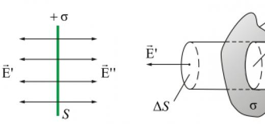
 WHAT METHODS WERE MEASURING THE SPEED OF LIGHT? The figure shows a diagram of the experiment with which Galileo proposed to measure the speed of light. Opening the shutter of the lantern, it was necessary to determine how long it would take the light to return, reflected from the mirror.
 THIS WAS THE FIRST KNOWN ATTEMPT TO EXPERIMENTALLY DETERMINE THE SPEED OF LIGHT BY GALILEO GALILEI. HOWEVER, THE SIGNAL DELAY IS NOT SUCCESSFUL TO DETECT BECAUSE OF THE HIGH SPEED OF LIGHT. The first experimental determination of the speed of light was made by the Danish astronomer Olaf Römer in 1675.
 The orbit of Io's satellite Io makes one revolution around Jupiter in 42.5 hours. As the Earth moves away from Jupiter, each subsequent eclipse of Io comes later than the expected moment. The total delay of the beginning of the eclipse when the Earth moved away from Jupiter by the diameter of the Earth's orbit later than the expected time was 22 min. Earth 3 Earth orbit I C S 2 II Römer experiment Jupiter orbit S 1
 By dividing the diameter of the earth's orbit by the delay time, the value of the speed of light was obtained: s = 3*1011 m / 1320 s s=2.27*10 8 m/s. The result obtained had a large error.
 THE FIRST LABORATORY MEASUREMENT OF THE SPEED OF LIGHT WAS PERFORMED IN 1849 BY THE FRENCH PHYSICIST ARMAND FIZO. In his experiment, the light from the source S passed through the interrupter K (the teeth of a rotating wheel) and, reflected from the mirror Z, returned again to the gear wheel.

 THE PHYSO INSTALLATION PARAMETERS ARE THESE. THE LIGHT SOURCE AND THE MIRROR WERE LOCATED IN THE HOUSE OF FATHER FIZO NEAR PARIS, AND THE MIRROR WAS ON MONTMARTRE. THE DISTANCE BETWEEN THE MIRRORS WAS ℓ ~ 8.66 KM, THE WHEEL HAD 720 TEETH. IT WAS ROTATING UNDER THE ACTION OF A CLOCK MECHANISM SET INTO MOVEMENT BY A LOSSING LOAD. USING A ROTATION COUNTER AND A CHRONOMETER, FIZO DISCOVERED THAT THE FIRST DARKNESS IS OBSERVED AT THE WHEEL ROTATION SPEED V = 12.6 RPM/S. LIGHT TRAVELING TIME T=2ℓ/C, THEREFORE GIVES C=3.14 10 8 M/S
 c = 3.14 10 8 m/s The value obtained from astronomical observations, but close to it. DESPITE THE SIGNIFICANT MEASUREMENT ERRORS, FIZO'S EXPERIENCE WAS OF HUGE IMPORTANCE - THE POSSIBILITY OF DETERMINING THE SPEED OF LIGHT BY "EARTHLY" MEANS WAS PROVEN.


 THE FINITENESS OF THE SPEED OF LIGHT IS PROVED EXPERIMENTALLY BY DIRECT AND INDIRECT METHODS. At present, with the help of laser technology, the speed of light is determined by measuring the wavelength and frequency of radio emission by methods independent of each other and is calculated by the formula: c \u003d λv Calculations give c \u003d 299792456.2 ± 1.1 m/s
 “HOW SPEEDS OF THE LIGHT? »c So far, there are no indications of change over time, but physics cannot unconditionally reject such a possibility. Well, it remains to wait for messages about new measurements of the speed of light. These measurements can give a lot more to the knowledge of nature, inexhaustible in its diversity.

 CONCLUSIONS: 1. The nature of light has corpuscular-wave dualism (duality). 2. It should be recognized scientific fact, established experimentally - the finiteness and absoluteness (invariance) of the speed of light in vacuum. 3. Confirmation of any physical theory is experimental facts.
optical radiation(or light in the broad sense of the word) are electromagnetic waves, the lengths of which are in the range from 10 -11 to 10 -2 m (from units to tenths of a mm) or the frequency range of which is approximately equal to 3 * 10 11 ... 3 * 10 17 Hz.
As for any other radiation, there is source of optical radiation and optical radiation receiver. The receiver of optical radiation can be, for example, the human eye. The human eye is able to perceive optical radiation with a wavelength of 400 to 760 nm. This is visible radiation. In addition to visible radiation, optical radiation also includes infrared radiation(with wavelength from 0.75 to 2000 µm) and ultraviolet radiation(with a wavelength from 10 to 400 nm). Light waves are studied using optical methods that have historically developed in the analysis of the laws of visible light.
In the 17th century, the first scientific hypotheses about the nature of light were made. Light has energy and carries it through space. Either bodies or waves can transfer energy, so two theories have been put forward about the nature of light.
Corpuscular theory of light(from the Latin corpusculum - particle) was proposed in 1672 by the English scientist Isaac Newton (1643 - 1727). According to this theory, light is a stream of particles that emits in all directions Light source. With the help of this theory, such optical phenomena as, for example, different colors of radiation were explained.
The Dutch scientist Christian Huygens (1629 - 1695) also created in the 17th century wave theory of light, according to which light has a wave nature. This theory explains things like interference, light diffraction etc.
Both of these theories existed in parallel for a long time, since neither of them separately could fully explain all optical phenomena. By the beginning of the 19th century, after the studies of the French physicist Augustin Jean Fresnel (1788 - 1827), the English physicist Robert Hooke (1635 - 1703) and other scientists, it became clear that the wave theory of light has an advantage over the corpuscular one. In 1801, the English physicist Thomas Young (1773 - 1829) formulated the principle of interference (the increase or decrease in illumination when light waves are superimposed on each other), which allowed him to explain the colors of thin films. Fresnel explained what is the diffraction of light (light bending around obstacles) and the straightness of light propagation.
Nevertheless, the wave theory of light had one significant drawback. It assumed that light radiation is a transverse mechanical wave, which can only occur in an elastic medium. Therefore, a hypothesis was created about the invisible world ether, which is a hypothetical medium that fills the entire Universe (the entire space between bodies and molecules). The world ether should have had a number of contradictory properties: it should have elastic properties solids and be weightless at the same time. These difficulties were resolved in the 2nd half of the 19th century with the consistent development of the teachings of the English physicist James Clerk Maxwell (1831 - 1879) about the electromagnetic field. Maxwell came to the conclusion that light is a special case of electromagnetic waves.
However, at the beginning of the 20th century, discontinuous, or quantum properties of light. These properties were explained by the corpuscular theory. Thus, light has corpuscular-wave dualism (duality of properties). In the process of propagation, light exhibits wave properties (that is, it behaves like a wave), and during radiation and absorption - corpuscular properties(that is, it behaves like a stream of particles).
The laws of light propagation in transparent media based on the concepts of a light beam are considered in the section of optics called. It is understood that a hundred light beam is a line along which the energy of light electromagnetic waves propagates.
The law of rectilinear propagation of light
In practice, light propagates in a straight line inside a limited cone, which is a light beam. The diameter of this light beam exceeds the wavelength of the light.
If a refractive index environment is the same everywhere, then such an environment is called optically homogeneous medium.
In a transparent homogeneous medium, light propagates in a straight line. This is what law of rectilinear propagation of light.
The straightness of light propagation is confirmed by many phenomena, for example, the appearance of a shadow from opaque bodies. If S is a very small light source, and M is an opaque body that blocks the path of the light S falling on it, then a shadow cone forms behind the body M. The light coming from the source is delayed by the body M, and on the screen, which is placed at right angles to the axis of the cone, a well-defined shadow of the body M is obtained (see Fig. 1.1).
Rice. 1.1. Straightness of light propagation.
Light sources of large dimensions (compared to the distance from the light sources to the obstacle) form a penumbra. The formation of penumbra can be considered using two small sources, which are located at a distance from each other equal to the size of a large light source. On fig. 1.2 shows a section of shadow cones that are formed by light behind the body M. A total shadow is formed behind the opaque body M in the area where no light from any light source hits.
Penumbra(partially illuminated space) is formed in the area where the rays pass from only one of the light sources. For example, in an area where the rays of only the source S1 pass, and the other light source S2 is obscured by the body M. If the light source is large, then each of its points can be considered as a point source of light. In this case, radiation from individual parts of the radiating surface will be added. Areas of shade and penumbra are also formed.

Rice. 1.2. Penumbra formed by a large light source.
The formation of a shadow when rays from a light source fall on an opaque object explains such phenomena as solar and lunar eclipses.
Such a property as straightness of light propagation, is used in determining distances on land, at sea and in the air, as well as in production when monitoring the straightness of products and tools by the line of sight.
The straightness of light propagation explains the possibility of obtaining images using a small aperture. The simplest device that allows you to observe the inverted image of objects is called pinhole camera and is a box with a small hole in the front wall. A beam of light that propagates in a straight line hits the rear wall of the camera obscura, where a light spot appears with the appropriate intensity. The totality of light spots from all points of an object creates an image of this object on the back wall of the camera obscura.
Lesson on the topic “The history of the development of views on the nature of light. The speed of light." 11th grade Khramova Anna Vladimirovna
"All possible ways it is necessary to ignite in children an ardent desire for knowledge and skill.
Ya. Kamensky
Physics lesson in grade 11 on the topic
Lesson type : lesson learning new material.
Lesson Form : lesson - theoretical study.
Lesson Objectives: to acquaint students with the history of the development of ideas about the nature of light and with ways to find the speed of light.
Lesson objectives:
Tutorials:
repetition of the basic properties of light, the formation of skills to explain physical phenomena based on the use of quantum or wave theory of light, the application of the idea of wave-particle duality.
Developing:
Generalization and systematization of the studied material, elucidation of the role of experience and theory in the formation quantum physics, explanation of the limits of applicability of theories, disclosure of corpuscular-wave dualism.
Educational:
show the infinity of the process of cognition, open spiritual world and human qualities of scientists, to acquaint with the history of the development of science, to consider the contribution of scientists to the development of the theory of light.
Equipment : multimedia installation, handouts.
Activities: group work, individual work, frontal work, independent work,work with literature or electronic sources of information, analysis of the results of working with text, conversation, written work.
The structure of an interactive lesson on the topic
Development of views on the nature of light. The speed of light."
Structural element lesson | Use my methods | Teacher roles | Student positions | Result | Time |
Immersion | I know / I want to know / I found out | Designer and organizer of a problematic creative situation | Subject of creative activity | Table with filled columns "I know", "I want to know" | 5 minutes |
Theoretical block | Two part diary | moderator of educational and research activities students | Subject of independent teaching and research activities | Table "Development of views on the nature of light" | 15 minutes |
Theoretical block | Group work (using the Logbook strategy) | Student Educational Inquiry Consultant | The subject of group learning activities | Table "Determination of the speed of light" | 20 minutes |
Reflection | I know / I want to know / I found out | Expert | Subject of independent activity | Table with filled columns "I know", "I want to know", "What I learned" | 5 minutes |
During the classes.
- Organizing time. Greetings, checking the readiness of students for the lesson.
- Announcement of the topic of the lesson and updating knowledge on this topic.
Teacher:
Guys, let's remember what we know on this topic?
Give examples of natural and artificial light sources.
What is a beam?
The law of rectilinear propagation of light.
What is a shadow?
What is penumbra?
The law of reflection of light.
Pupils are invited to fill in the first column "I know" of the table ZHU (Appendix 1).
In everyday speech, we use the word "light" in the most different meanings: my light, my sun, tell me... learning is light, and ignorance is darkness... In physics, the term "light" has a much more definite meaning. So what is light? And what would you like to know about light phenomena? Please fill in the second column of the ZHU table yourself.
- Setting the goal and objectives of the lesson (based on the result of a joint analysis of the ZHU table).
- Theoretical block "Development of views on the nature of light."
The students are given the text “Development of views on the nature of light” (Appendix 2). The task is to familiarize yourself with the text, analyze it and compile a two-part diary (Appendix 3).
- Discussion of the result of working with the text.
- Wording problem situation"How to measure the speed of light?"
The famous American scientist Albert Michelson spent most of his life measuring the speed of light.
Once a scientist examined the alleged path of a light beam along the canvas railway. He wanted to build an even better setup for an even more accurate method of measuring the speed of light. Before that, he had already worked on this problem.
several years and achieved the most accurate values for that time. Newspaper reporters became interested in the behavior of the scientist and, perplexed, asked what he was doing here. Michelson explained that he was measuring the speed of light.
What for? - the question followed.
Because it's devilishly interesting," Michelson replied.
And no one could have imagined that Michelson's experiments would become the foundation on which the majestic edifice of the theory of relativity would be built, giving a completely new idea of the physical picture of the world.
Fifty years later, Michelson was still continuing his measurements of the speed of light.
Once the great Einstein asked him the same question,
Because it's damn interesting! Michelson and Einstein answered half a century later.
The teacher asks the question: “Is it important to know the speed of light, other than that it’s just “devilishly interesting”?
The opinions of students are heard, where knowledge about the speed of light is applied.
- Theoretical block "Measuring the speed of light".
The teacher divides the class in advance into creative groups to study various methods for measuring the speed of light:
- Roemer Method group
- Fizeau Method Group
- Foucault Method Group
- Bradley Method Group
- Michelson method group
Each group provides a report + presentation on the studied material according to the plan:
- Date of the experiment
- Experimenter
- The essence of the experiment
- The found value of the speed of light.
The rest of the students fill in the table on their own during the performance of the groups (Appendix 4). The layout of the table is prepared in advance.
The teacher sums up.
What was the main difficulty in measuring the speed of light?
What is the approximate speed of light in vacuum?
Modern physics decisively asserts that the history of the speed of light is not over. Evidence of this is the work on measuring the speed of light, carried out in recent years.
A certain result of measuring the speed of light in the microwave range was the work of the American scientist K. Frum, the results of which were published in 1958. The scientist got the result of 299792.50 kilometers per second. For a long period, this value was considered the most accurate.
In order to improve the accuracy of determining the speed of light, it was necessary to create fundamentally new methods that would allow measurements in the region of high frequencies and, accordingly, shorter wavelengths. The possibility of developing such methods appeared after the creation of optical quantum generators - lasers. The accuracy of determining the speed of light has increased in relation to Frum's experiments by almost 100 times. The method of determining frequencies using laser radiation gives the value of the speed of light equal to 299792.462 kilometers per second.
Physicists continue to investigate the question of the constancy of the speed of light over time. Studies of the speed of light can give much more to the knowledge of nature, inexhaustible in its diversity. 300-year history of the fundamental constant with clearly show its relationship with critical issues physics.
Teacher: - What conclusion can we draw about the significance of the value of the speed of light?
Students: - The measurement of the speed of light enabled the further development of physics as a science.
- Reflection. Filling in the column "Learned" in the ZHU table.
Homework.Section 59 (G.Ya. Myakishev, B.B. Bukhovtsev “Physics. 11”)
Problem solving
1. From the ancient Greek legend of Perseus:
“No further than the flight of an arrow was a monster when Perseus flew high into the air. His shadow fell into the sea, and with fury the monster rushed at the shadow of the hero. Perseus boldly rushed from a height to the monster and deeply plunged a curved sword into his back ... "
Question: what is a shadow and due to what physical phenomenon is it formed?
2. From the African fairy tale “The Election of the Leader”:
“Fellows,” said the Stork, stepping sedately into the middle of the circle. We've been arguing since morning. Look, our shadows have already shortened and will soon disappear completely, for noon is approaching. So let's come to some decision before the sun passes its zenith ... "
Question: why did the lengths of the shadows cast by people become shorter? Explain your answer with a drawing. Is there a place on Earth where the change in the length of the shadow is minimal?
3. From the Italian fairy tale “The Man Who Was Looking for Immortality”:
“And then Grantesta saw something that seemed to him more terrible than a storm. A monster was approaching the valley, flying faster than a beam of light. It had leathery wings, a warty soft belly and a huge mouth with protruding teeth…”
Question: what is wrong from the point of view of physics in this passage?
4. From the ancient Greek legend of Perseus:
“Perseus quickly turned away from the Gorgons. He is afraid to see their formidable faces: after all, one look and he will turn to stone. Perseus took the shield of Pallas Athena - as the Gorgons were reflected in the mirror. Which one is Medusa?
As an eagle falls from the sky to the intended victim, so Perseus rushed to the sleeping Medusa. He looks into a clear shield in order to more accurately strike ... "
Question: what physical phenomenon Perseus used to behead Medusa?
Appendix 1.
Table "Know / Want to know / Learned"
Appendix 2
The history of the development of views on the nature of light
The first ideas about the nature of light were laid down in ancient times. The Greek philosopher Plato (427-327 BC) created one of the first theories of light.
Euclid and Aristotle (300-250 BC) empirically established such basic laws of optical phenomena as the rectilinear propagation of light and the independence of light beams, reflection and refraction. Aristotle first explained the essence of vision.
Despite the fact that the theoretical positions of the ancient philosophers, and later the scientists of the Middle Ages, were insufficient and contradictory, they contributed to the formation of correct views on the essence of light phenomena and laid the foundation for the further development of the theory of light and the creation of various optical instruments. With the accumulation of new research on the properties of light phenomena, the point of view on the nature of light has changed. Scientists believe that the history of the study of the nature of light should begin from the 17th century.
In the 17th century, the Danish astronomer Remer (1644–1710) measured the speed of light propagation, the Italian physicist Grimaldi (1618–1663) discovered the phenomenon of diffraction, the brilliant English scientist I. Newton (1642–1727) developed the corpuscular theory of light, discovered the phenomena of dispersion and interference, E. Bartholin (1625–1698) discovered double refraction in Icelandic spar, thus laying the foundations of crystal optics. Huygens (1629–1695) laid the foundation for the wave theory of light.
In the 17th century, the first attempts were made to theoretically substantiate the observed light phenomena. The corpuscular theory of light, developed by Newton, is that light radiation is considered as a continuous stream of tiny particles - corpuscles, which are emitted by a light source and fly at high speed in a homogeneous medium in a straight line and uniformly.
From the point of view of the wave theory of light, the founder of which is H. Huygens, light radiation is a wave motion. Huygens considered light waves as high-frequency elastic waves propagating in a special elastic and dense medium - ether, which fills all material bodies, the gaps between them and interplanetary spaces.
The electromagnetic theory of light was created in the middle of the 19th century by Maxwell (1831–1879). According to this theory, light waves are of an electromagnetic nature, and light radiation can be considered as a special case electromagnetic phenomena. Research by Hertz and later by P.N. Lebedev also confirmed that all the basic properties of electromagnetic waves coincide with the properties of light waves.
Lorentz (1896) established the relationship between radiation and the structure of matter and developed the electronic theory of light, according to which the electrons that make up atoms can oscillate with a known period and, under certain conditions, absorb or emit light.
Maxwell's electromagnetic theory, combined with Lawrence's electronic theory, explained all the then known optical phenomena and seemed to fully reveal the problem of the nature of light.
Light emissions were considered as periodic oscillations of electric and magnetic forces propagating in space at a speed of 300,000 kilometers per second. Lawrence believed that the carrier of these vibrations, the electromagnetic ether, has the properties of absolute immobility. However, the created electromagnetic theory soon proved to be untenable. First of all, this theory did not take into account the properties of the real environment in which electromagnetic oscillations. In addition, this theory could not explain a number of optical phenomena encountered by physics at the turn of the 19th and 20th centuries. These phenomena include the processes of emission and absorption of light, black body radiation, the photoelectric effect, and others.
The quantum theory of light arose at the beginning of the 20th century. It was formulated in 1900 and substantiated in 1905. The founders of the quantum theory of light are Planck and Einstein. According to this theory, light radiation is emitted and absorbed by particles of matter not continuously, but discretely, that is, in separate portions - light quanta.
Quantum theory is like new form revived the corpuscular theory of light, but in essence it was the development of the unity of wave and corpuscular phenomena.
As a result historical development modern optics has a substantiated theory of light phenomena, which can explain the various properties of radiation and allows us to answer the question of under what conditions certain properties of light radiation can manifest themselves. Modern theory light confirms its dual nature: wave and corpuscular.
Result (km/s)
1676
Römer
Moons of Jupiter
214000
1726
Bradley
stellar aberration
301000
1849
fizo
Gear
315000
1862
Foucault
rotating mirror
298000
1883
Michelson
rotating mirror
299910
1983
accepted value
299 792,458
Page
DEVELOPMENT OF VIEWS ON THE NATURE OF LIGHT
Two Ways to Pass Interactions
Corpuscular and wave theories of light
THE PHENOMENON OF LIGHT INTERFERENCE
Addition of two monochromatic waves
Conditions for maxima and minima of the interference pattern
interference pattern
Why light waves from two sources are not coherent
Idea of Augustin Fresnel
Fresnel biprism
Dimensions of light sources
Light Wavelength
Wavelength and color of light perceived by the eye
THE PHENOMENON OF INTERFERENCE IN THIN FILMS
Thomas Young's idea
Localization of interference fringes
NEWTON'S RINGS
Wavelength change in matter
Why films need to be thin
SOME APPLICATIONS OF INTERFERENCE
Michelson experiment
Surface quality check
Enlightenment of optics
interference microscope
Stellar interferometer
radio interferometer
Bibliography
DEVELOPMENT OF VIEWS ON THE NATURE OF LIGHT
The first ideas of the ancient scientists about what light is were very naive. It was believed that special thin tentacles come out of the eyes and visual impressions arise when they feel objects. Of course, there is no need to dwell on such views in detail, but it is necessary to trace briefly the development of scientific ideas about what light is.
Two Ways to Pass Interactions
From the source, the light spreads in all directions and falls on the surrounding objects, causing, in particular, their heating. When light enters the eye, it causes visual sensations - we see. It can be said that when light propagates, influences are transferred from one body (light source) to another body (light receiver).
In general, the action of one body on another can be carried out by two different ways: either through the transfer of matter from a source to a receiver, or through a change in state environment, in which the bodies are located, i.e. no material transfer.
You can, for example, make a bell ring, located at some distance, by successfully hitting it with a ball. Here we are dealing with the transfer of matter. But you can do otherwise: tie the cord to the tongue of the bell and make the bell ring, sending waves along the cord, swinging its tongue. In this case, no material transfer occurs. Waves propagate along the cord, i.e. the shape of the line changes. Thus, the action from one body to another can be transmitted by means of waves.
Corpuscular and wave theories of light
In accordance with the two possible ways of transmitting action from the source to the receiver, two completely different theories arose and began to develop about what light is, what its nature is. Moreover, they arose almost simultaneously in the 17th century. One of these theories is associated with the name of the English physicist Isaac Newton, and the other with the name of the Dutch physicist Christian Huygens.
Newton adhered to the so-called corpuscular (from the Latin word korpusculum - particle) theory of light, according to which light is a stream of particles propagating from a source in all directions (i.e., the transfer of matter). According to Huygens' ideas, light is waves propagating in a special, hypothetical medium - ether, which fills all space and penetrates into the interior of all bodies.
Both theories have existed in parallel for a long time. None of them could win a decisive victory. Only the authority of Newton forced the majority of scientists to give preference to the corpuscular theory. The experimentally discovered laws of light propagation known at that time were more or less successfully explained by both theories. On the basis of the corpuscular theory, it was difficult to explain why light beams, crossing in space, do not act on each other in any way. After all, light particles must collide and scatter.
The wave theory explained this easily. Waves, for example, on the surface of water, freely pass through each other without mutual influence. However, the rectilinear propagation of light, leading to the formation of sharp shadows behind objects, is difficult to explain based on the wave theory. According to the corpuscular theory, the rectilinear propagation of light is simply a consequence of the law of inertia. This indeterminate position regarding the nature of light lasted until early XIX century, when the phenomena of light diffraction (enveloping light around obstacles) and light interference (intensification or weakening of light when light beams are superimposed on each other) were discovered. These phenomena are inherent exclusively in wave motion. It is impossible to explain them with the help of corpuscular theory. Therefore, it seemed that the wave theory had won a final and complete victory.
Such confidence was especially strengthened when the English physicist James Clerk Maxwell proved in the second half of the 19th century that light is a special case of electromagnetic waves. Maxwell's work laid the foundations for the electromagnetic theory of light.
After the experimental discovery of electromagnetic waves at the end of the 19th century by the German physicist Heinrich Hertz, there was no doubt that light behaves like a wave during propagation. However, at the beginning of the 20th century, ideas about the nature of light began to change radically. It suddenly turned out that the rejected corpuscular theory is still relevant to reality.
It turned out that during emission and absorption, light behaves like a stream of particles. Discontinuous, or, as physicists say, quantum, properties of light have been discovered. An unusual situation arose: the phenomena of interference and diffraction could still be explained by considering light as a wave, and the phenomena of radiation and absorption could be explained by agreeing that light is a stream of particles. These two seemingly incompatible ideas about the nature of light in the 30s of the 20th century were successfully combined in a new physical theory - quantum electrodynamics. Over time, it became clear that the duality of properties is inherent not only in light, but also in any other form of matter. So, in order to be sure that light has a wave nature, it is necessary to find experimental evidence of the interference and diffraction of light.
THE PHENOMENON OF LIGHT INTERFERENCE
It is known that for observations of the interference of transverse mechanical waves two sources of waves were used on the surface of the water (for example, two balls fixed on an oscillating rocker). It is impossible to obtain an interference pattern (alternating illumination minima and maxima) using two natural independent light sources, for example, two electric light bulbs. The inclusion of another light bulb only increases the illumination of the illuminated surface. Let's find out what is the reason for this.
Addition of two monochromatic waves
Let's see what happens as a result of adding two traveling waves with the same oscillation frequencies. It is known that harmonic light waves are called monochromatic. Let these waves propagate from two point sources S1 and S2 located at a distance from each other. The result of wave addition will be considered at a distance from the sources much greater (i.e.). The screen on which the light waves fall is placed parallel to the line connecting the sources (see Figure 1).
A light wave is, according to the electromagnetic theory of light, an electromagnetic wave. In an electromagnetic wave propagating in a vacuum, the tension electric field modulo, in the Gauss system, is equal to the magnetic induction. We will consider the addition of electric field strength waves. However, the traveling wave equation has the same form for waves of any physical nature.
So, sources S1 and S2 emit two spherical monochromatic waves. The amplitudes of these waves decrease with distance. However, if we consider the summation of waves at distances r1 and r2 from the sources, many long distances between sources (i.e., and), then the amplitudes from both sources can be considered equal.
The waves that came from sources S1 and S2 to point A of the screen have approximately the same amplitudes and the same frequencies ω of oscillations. AT general case the initial phases of oscillations in wave sources may differ. Running equation spherical wave in general it can be written like this:
where φ0 is the initial phase of oscillations in the source ().
When two waves are added at point A, the resulting harmonic oscillation tension:
Here we consider that the fluctuations of the intensities and occur along one straight line. Denote by:
The initial phase of the oscillations of the first wave at point A, and after: - initial phase oscillations of the second wave at the same point. Then:
for the phase difference we obtain the expression:
The amplitude of the resulting tension fluctuations at point A is equal to:
It is known that the radiation intensity I is directly proportional to the square of the amplitude of the intensity fluctuations, which means for one wave: I ~ E , and for the resulting fluctuations: I ~ E . Therefore, for the wave intensity at point A we have:
Conditions for maxima and minima of the interference pattern
The intensity of light at a given point in space is determined by the phase difference of the oscillations φ 1 - φ 2. If the oscillations of the sources are in phase, then φ 01 - φ 02 = 0 and: The phase difference is determined by the difference in distances from the sources to the observation point. Recall that the difference in distances is called the difference in the path of interfering waves from their sources. At those points in space for which next condition:
K=0, 1, 2… (3) the waves cancel each other out (I = 0). As a result, an interference pattern appears in space, which is an alternation of maxima and minima of the light intensity, and hence the illumination of the screen. The conditions for interference maxima (see formula 3) and minima (see formula 4) are exactly the same as in the case of mechanical wave interference. interference pattern If any plane is drawn through the sources, then the intensity maximum will be observed at points of the plane that satisfy the condition: These points lie on a curve called a hyperbola. It is for a hyperbola that the condition is fulfilled: the difference in distances from any point on the curve to two points, called the foci of the hyperbola, is a constant value. A family of hyperbolas is obtained, corresponding to different values of k, when the light sources are the foci of the hyperbola. When the hyperbola rotates around the axis passing through the sources S1 and S2, two surfaces are obtained that form a two-cavity hyperboloid of revolution (see Figure 2), when different values of k correspond to different hyperboloids. The interference pattern on the screen depends on the location of the screen. The shape of the interference fringes is given by the lines of intersection of the screen plane with these hyperboloids. If the screen A is perpendicular to the line l connecting the light sources S1 and S2 (see figure 2), then the interference fringes are in the form of circles. If the screen B is located parallel to the line connecting the light sources S1 and S2, then the interference fringes will be hyperbolas. But these hyperbolas at a large distance D between the light sources and the screen near the point O can be approximately considered as segments of parallel lines. Let's find the distribution of light intensity on the screen (see Figure 1) along the straight line MN parallel to the line S1S2 . To do this, we find the dependence of the phase difference (see formula 2) on the distance: h=OA. Applying the Pythagorean theorem to triangles and, we get: Subtracting term by term from the first equality the second, we find: Considering l< Light intensity (see formula 1) changes with h: A plot of this function is shown (see figure 3). The intensity changes periodically and reaches maxima under the condition: K=0, 1, 2,… (6) The value hk determines the position of the maximum number k. Distance between adjacent peaks: It is directly proportional to the light wavelength λ and the greater, the smaller the distance l between the light sources compared to the distance D to the screen. In reality, the intensity will not be constant from one interference maximum to another interference maximum, and does not remain constant along one interference fringe. The fact is that the amplitudes of light waves from light sources S1 and S2 are exactly equal, only at point O. At other points they are only approximately equal. As in the case of mechanical waves, the formation of an interference pattern does not mean the transformation of light into any other forms. It is only redistributed in space. The average value of the total light intensity is equal to the sum of the intensities from the two light sources. Indeed, the average value of the light intensity over the entire length of the interference pattern (see formula 5) is equal to 2I0, since the average value of the cosine for all possible values of the argument depending on h is zero. Why light waves from two sources are not coherent The interference pattern from two sources, which we have described, arises only when monochromatic waves of the same frequency are added. For monochromatic waves, the phase difference of oscillations at any point in space is constant. Waves with the same frequency and constant phase difference are called coherent. Only coherent waves, superimposed on each other, give a stable interference pattern with an invariable arrangement in space of the maxima and minima of the oscillations. Light waves from two independent sources are not coherent. Atoms of sources radiate light independently from each other as separate "pieces" (i.e., trains) of sinusoidal waves. The duration of continuous radiation of an atom is about 10 -8seconds. During this time, the light travels a path about 3m long (see Figure 4). These trains of waves from both sources are superimposed on each other. The phase difference of oscillations at any point in space changes chaotically with time depending on how the trains from different sources are shifted relative to each other at a given time. Waves from different light sources are not coherent due to the fact that the difference in the initial phases does not remain constant (the exception is quantum light generators - lasers created in 1960). Phases φ 01and φ 02change randomly, and because of this, the phase difference of the resulting oscillations at any point in space randomly changes. With random "breaks" and "occurrence" of oscillations, the phase difference changes randomly, taking all possible values from 0 to 2 during the observation time π . As a result, over time τ , much longer than the time of irregular phase changes (on the order of 10 -8seconds), the average value cos( φ 1-φ 2) in the intensity formula (see formula 1) is zero. The intensity of the light turns out to be equal to the sum of the intensities from the individual sources, and no interference pattern will be observed. The incoherence of light waves is the main reason why light from two sources does not give an interference pattern. This is the main, but not the only reason. Another reason is that the wavelength of light, as we shall soon see, is very, very short. This greatly complicates the observation of interference, even if one has coherent wave sources. So, in order for a stable interference pattern to be observed when light waves are superimposed, it is necessary that the light waves be coherent, i.e. have the same wavelength and constant phase difference. Idea of Augustin Fresnel To obtain coherent light sources, the French physicist Augustin Fresnel found in 1815 a simple and ingenious way. It is necessary to divide the light from one source into two beams and, having forced them to go through different paths, bring them together. Then the train of waves emitted by an individual atom will be divided into two coherent trains. This will be the case for trains of waves emitted by each atom of the source. The light emitted by a single atom gives a certain interference pattern. When these pictures are superimposed on each other, a fairly intense distribution of illumination on the screen is obtained: the interference pattern can be observed. There are many ways to obtain coherent light sources, but their essence is the same. By dividing the beam into two parts, two imaginary light sources are obtained, giving coherent waves. To do this, use two mirrors (Fresnel bimirrors), Fresnel biprisms (two prisms folded at the bases), a bilens (a lens cut in half with halves apart) and much more. And now we will take a closer look at one of the devices. Fresnel biprism A Fresnel biprism consists of two prisms with small refractive angles stacked together (see Figure 5). Light from the source S falls on the upper faces of the biprism, and after refraction, two light beams appear. The continuations of the rays refracted by the upper and lower prisms in the opposite direction intersect at two points S 1and S 2, which are imaginary images of the source S. For small refractive angles θ prisms, the source and its two imaginary images lie practically in the same plane. The waves in both beams are coherent, since in fact they are emitted by the same source. Both beams are superimposed on each other and interfere. There is an interference pattern, described earlier. A very clear proof that we are dealing with interference is a simple change in the experiment. If one half of the biprism is covered with an opaque screen, then the interference pattern disappears, since no superposition of waves occurs. The distance between the interference fringes (see formula 7) depends on the length of the interfering waves λ , distances b from the biprism to the screen, distances l between imaginary light sources. Let's calculate this distance. To calculate l, it is easiest to consider the course of a beam incident on a prism normally (i.e., perpendicular to its surface). There is no such ray in reality, but it can be constructed by mentally continuing the refractive face of the prism (see Figure 6). The continuations of all rays incident on the face of the prism intersect at the point S1 - the imaginary source. As can be seen from the figure, and, where a is the distance from the source to the biprism. According to the law of refraction for small angles: . (The angles are small when the refractive angle of the prism is small and when a is much larger than the size of the biprism.) Distance: The distance between the interfering fringes (see formula 8) is: where b is the distance from the biprism to the screen. Thus, the smaller the refractive angle of the prism θ, the greater the distance between the interference maxima. Accordingly, the interference pattern is easier to observe. That is why the biprism must have small refractive angles. Dimensions of light sources To observe interference using a biprism and similar devices, the geometric dimensions of the light source must be small. The fact is that groups of atoms on the left, for example, part of the source, give their own interference pattern, and the right - their own. These pictures are offset from each other (see Figure 7). With a large light source, the maxima of one interference pattern will coincide with the minima of another interference pattern, and as a result, the interference pattern will be “smeared” (i.e., the screen illumination will become uniform). Light Wavelength The interference pattern allows you to determine the wavelength of light. This can be done, in particular, in experiments with a biprism. Knowing the distances a and b, as well as the refractive angle of the biprism θ and its refractive index n, by measuring the distances between the interference maxima Δ h, you can calculate the wavelength of light (see formula 8). When the biprism is illuminated with white light, only the central maximum remains white, and all other maxima have a “rainbow” color. Closer to the center of the interference pattern, a purple color appears, and further away from the center of the interference pattern, a red color appears. This means (see formula 6) that the wavelength of light perceived by the eye as red is maximum, and the wavelength of light perceived by the eye as violet is minimum. Distance of the interference maximum from the center: Only at k=0, hk=0 for all wavelengths, so the "zero" maximum is not "rainbow", but white. It is easy to detect the dependence of the color of the light perceived by the eye on the wavelength of light by placing various light filters in the path of the white light incident on the biprism. The distances between peaks for red light rays are greater than for yellow light rays, than for green light rays and all other colors of rays. Measurements are given for red light meters, and for purple light meters. Wavelengths corresponding to other colors of the spectrum have intermediate values to the above-mentioned light wavelengths. For any color, the wavelength of light is very, very small. Some visual representation of the wavelength of light can be obtained from the following comparison. If a sea wave, a few meters long, would increase as many times as the number of times it would be necessary to increase the length of a light wave in order for it to equal the width of this report on my term paper, then the entire Atlantic Ocean (from New York in the USA to Lisbon in Portugal) only one sea wave would fit. But still, the length of light rays is about a thousand times greater than the diameter of one atom, which is approximately equal to m. Wavelength and color of light perceived by the eye The phenomenon of interference not only proves that light has wave properties, but also allows you to measure the wavelength of light. At the same time, it turns out that just as the pitch of sound perceived by the ear is determined by the frequency of propagating mechanical vibrations, the color of light perceived by the eye is determined by the frequency of propagating electromagnetic oscillations belonging to the "Visible light" range. Knowing on what physical characteristic of a light wave the color perception of light depends, it is possible to give a deeper definition of the phenomenon of light dispersion. Dispersion should be called the dependence of the refractive index of an optically transparent medium not on the color of the propagating light, but on the frequency of propagating electromagnetic oscillations. There are no colors outside of us in nature, there are only electromagnetic oscillations of various frequencies, propagating in the form of electromagnetic waves of various lengths. The eye is a complex physical device capable of distinguishing small (about 10 -6cm) the difference in the length of light waves. Interestingly, most animals, including dogs, are unable to distinguish colors, but only distinguish the intensity of light, i.e. they see a black and white picture, as in a non-color movie or on a non-color TV screen. Color blind people also do not distinguish colors. THE PHENOMENON OF INTERFERENCE IN THIN FILMS So, Fresnel came up with a method for obtaining coherent waves to observe the phenomenon of light interference. However, he was not the first to observe the phenomenon of interference, and he was not the one who discovered the phenomenon of light interference for mankind. Some curiosity was that the phenomenon of light interference was observed a very long time ago, but they just did not realize it. Many have had to observe an interference pattern many times, when in childhood, having fun blowing soap bubbles, they saw iridescent overflows with all the colors of the rainbow, or repeatedly had a similar picture on the surface of water covered with a thin film of oil products. Thomas Young's idea The English physicist Thomas Young was the first to come up with a brilliant idea in 1802 about the possibility of explaining the colors of thin films by superimposing light waves, one of which is reflected from the outer surface of the film, and the second from the inner one. (In fairness, it should be noted that when publishing his work on the phenomenon of interference, Fresnel did not know anything about the work of Jung) Light waves, since they are emitted by one atom S of an extended light source (see Figure 8). Light waves 1 and 2 amplify or attenuate each other depending on the path difference. This path difference Δr arises from the fact that light wave 2 travels an additional path AB + BC inside the film, while light wave 1 travels only an additional distance DC. It is easy to calculate that, neglecting the refraction of light (i.e.), the path difference: where h is the film thickness, α is the angle of incidence of light. Light amplification occurs if the path difference Δr of light waves 1 and 2 is equal to an integer number of wavelengths, and light attenuation occurs when the path difference Δr is equal to an odd number of half-wavelengths. Light waves corresponding to different colors have different wavelengths. For the mutual damping of longer light waves, a greater film thickness is “needed” than for the mutual damping of shorter light waves. Therefore, if the film has a different thickness in different places, then different colors should appear when the film is illuminated with white light. The phenomenon of interference in thin films is observed when their surface is illuminated by very extended light sources, even when a cloudy sky is illuminated by scattered light. There is no need for strict restrictions on the size of the source, as in Fresnel's experiments with a biprism and other devices. But on the other hand, in Fresnel's experiments, the interference pattern is not localized. The screen behind the biprism (see Figure 5) can be placed anywhere where light beams from imaginary sources overlap. The interference pattern in thin films is already localized in a certain way, since in order to observe it on the screen, it is necessary to obtain an image of the film surface on it using a lens, because during visual observation, the image of the film surface is obtained on the retina of the eye. In this case, light rays from different parts of the source, falling on the same place on the film, are then collected on the screen (or on the retina) together (see Figure 9). For any pair of light rays, the path difference is approximately the same, since the film thickness is the same for them, and the angles of incidence differ very slightly. Rays with very different angles of incidence will not fall into the lens, and even more so into the pupil of the eye, which has very small dimensions. Since for all sections of the film of equal thickness the difference in the path of the interfering rays is the same, therefore, the illumination of the screen on which the image of these sections is obtained is also the same. As a result, stripes are visible on the screen, each of which corresponds to the same film thickness. Therefore, they (bands) are called so - strips of equal film thickness. If the surface of the light source is focused on the screen, then the light rays from this area of the surface of the light source fall into the same point on the screen after reflection from different areas of the surface of the film having different thicknesses (see Figure 10). Therefore, the interference pattern on the screen turns out to be blurry, since for different pairs of light rays the path difference is different due to different film thicknesses. NEWTON'S RINGS A simple interference pattern occurs in a thin layer of air between a glass plate and a plano-convex lens with a large radius of curvature placed on it. This interference pattern of lines of equal thickness has the form of concentric rings called Newton's rings. Let's take a lens with a large focal length F (and, consequently, with a small curvature of its convex surface) and put its convex side on a flat glass plate. Carefully examining the surface of the lens (preferably through a magnifying glass), we will find a dark spot at the point of contact between the lens and the plate and small iridescent rings around it. The distance between adjacent rings decreases rapidly as their radius increases (see photo 1). These are Newton's rings. They were first discovered by the English physicist Robert Hooke, and Newton studied them not only in white light, but also when the lens was illuminated with single-color (i.e., monochromatic) light. It turned out that the radii of the rings grow in proportion to the square root of the serial number of the ring, and the radii of the rings of the same serial number increase when moving from the violet end of the visible light spectrum to red (see photos 2 and 3). Newton could not explain why rings arise, since he was an ardent supporter of the corpuscular theory of light. Jung succeeded in doing this for the first time on the basis of the phenomenon of interference. Let us calculate the radii of Newton's dark rings. To do this, you need to calculate the path difference of two rays reflected from the convex surface of the lens at the "glass-air" interface and from the surface of the plate at the "air-glass" interface (see Figure 11). Radius r k ring number k is related to the thickness of the air gap by a simple relationship. According to the Pythagorean theorem (see Figure 12): where R is the radius of curvature of the lens. Since the radius of curvature of the lens is large compared to h, then h< The second light wave travels a path 2hk longer than the first. However, the path difference turns out to be larger than 2hk. When reflecting a light wave, as well as when reflecting a mechanical wave, a change in the phase of oscillations by π can occur, which means an increase in the difference by an additional . It turns out that when a light wave is reflected at the boundary of a medium with a high refractive index, the oscillation phase changes by π. (The same thing happens with a mechanical wave traveling along a rubber cord, the other end of which is rigidly fixed.) When reflected from an optically less dense medium, the phase of oscillations does not change. In this case, the phase of the light wave changes only upon reflection from the glass plate. Taking into account the additional increase in the path difference, the condition of minima of the interference pattern will be written as follows: K=0, 1, 2,… (10) Substituting expression (8) for hk into this formula, we determine the radius of the dark ring k depending on λ and R: The dark ring in the center (k=0, hk=0) is due to the phase change by π upon reflection from the glass plate. The radii of light rings are determined by the expression: K=0, 1, 2,… (12) Wavelength change in matter It is known that when light passes from one medium to another, the wavelength changes. It can be found like this. Let us fill the air gap between the lens and the plate with water or another transparent liquid with a refractive index n. The radii of the interference rings will decrease. Why is this happening? We know that when light passes from vacuum to any medium, the speed of light decreases by n times. Since, then either the frequency or the length of the light wave should decrease. But the radii of the rings depend on the wavelength of the light. Therefore, when light enters a medium, it is the wavelength that changes n times, not the frequency. Why films need to be thin When observing interference in thin films, there are no restrictions on the size of the light source, but there are restrictions on the thickness of the film. In window glass, we will not see an interference pattern similar to that given by thin films of kerosene and other liquids on the surface of water. Look again at photo 1 of Newton's rings in white light. As you move away from the center, the thickness of the air gap increases. In this case, the distances between the interference maxima decrease, and with a sufficiently large thickness of the interlayer, the entire interference pattern is smeared, and the rings are not visible at all. The fact that the difference between the radii of neighboring rings decreases with increasing order of the spectrum k follows from formulas 9 and 10. But it is not clear why the interference pattern disappears at all at large k, i.e. at large thicknesses of the air gap h. The point is that light is never strictly monochromatic. It is not an infinite monochromatic wave that falls on the film (or an air gap), but a finite train of waves. The less monochromatic the light, the shorter the train. If the train length is less than twice the film thickness, then light waves 1 and 2 reflected from the film surfaces will never meet (see Figure 13). Let us determine the film thickness at which interference can still be observed. Non-monochromatic light consists of waves of different wavelengths. Let us assume that the spectral interval is equal to Δλ, i.e. all wavelengths from λ to λ+Δλ are present. Then each value of k corresponds not to one interference line, but to a multi-colored stripe. In order for the interference pattern not to be smeared, it is necessary that the fringes corresponding to neighboring values of k do not overlap. In the case of Newton's rings, it is necessary that. Substituting the radii of the rings from formula 13, we get: This results in the condition: If, then k must be large and: So, the width of the spectral interval should be much less than the light wavelength λ divided by the order of the spectrum k. This relation is valid not only for Newton's rings, but also for interference in any thin films. SOME APPLICATIONS OF INTERFERENCE The applications of interference are very important and extensive. There are special devices - interferometers, the operation of which is based on the phenomenon of interference. Their purpose may be different: Accurate measurements of the lengths of light waves, measurement of the refractive index of gases, and others. Special purpose interferometers are available. About one of them, designed by Michelson to capture very small changes in the speed of light. Michelson experiment In 1881, the American physicist Albert Abraham Michelson conducted an experiment to test the hypothesis of the Dutch theoretical physicist Hendrik Anton Lorentz, according to which there should be a chosen frame of reference associated with the world ether, which is in absolute rest. The essence of this experiment can be understood with the help of the following example. From city A, the plane flies to cities B and C (see Figure 14, a). The distances between the cities are the same and equal to l=300 km, and the AB route is perpendicular to the AC route. The speed of the aircraft relative to the air c=200 km/h. Let the wind blow in the direction AB with a speed υ =10 km/h. The question is: which flight will take longer: from A to B and back, or from A to C and back? In the first case, the flight time is: In the second case, the plane should keep heading not for the city C itself, but for some point D, lying against the wind (see Figure 14, b). The aircraft will fly a distance AD relative to the air. The airflow blows the plane a DC distance. The ratio of these distances is equal to the ratio of speeds: Relative to the Earth, the aircraft will fly the distance AC. Since (see Figure 14 b), then. But: therefore. Therefore, the time t2 taken by the aircraft to cover this path back and forth at speed c is determined as follows: There is a time difference. Knowing it, as well as the distance AC and speed c, it is possible to determine the wind speed relative to the Earth. A simplified diagram of Michelson's experiment is shown in Figure 15. In this experiment, the role of an aircraft is played by a light wave with a speed of 300,000 km/s relative to the ether. (There was no doubt about the existence of the ether at the end of the 19th century.) The role of the ordinary wind was played by the alleged "ether wind" blowing around the Earth. Relative to the motionless ether, the Earth cannot be at rest all the time, since it moves around the Sun at a speed of about 30 km/s, and this speed continuously changes direction. The role of city A was played by a translucent plate P, dividing the light flux from the source S into two mutually perpendicular beams. Cities B and C are replaced by mirrors M 1them 2, directing the light beams back. Further, both beams were connected and fell into the objective of the telescope. In this case, an interference pattern appeared, consisting of alternating light and dark stripes (see Figure 16). The location of the lanes depended on the time difference, on one and on the other path. The interferometer was mounted on a square stone slab with sides of 1.5 m and a thickness of more than 30 cm. The slab was floating in a bowl of mercury so that it could be rotated around a vertical axis without shaking (see Figure 17). The direction of the "ethereal wind" is unknown. But when the interferometer rotates, the orientation of the light paths of the OM 1and OM 2(see Figure 15) relative to the "ethereal wind" should have changed. Therefore, the difference in the times of passage of the OM paths should have changed 1and OM 2, and therefore the interference fringes in the field of view of the tube should also have shifted. It was hoped to determine the speed of the "ethereal wind" and its direction from this shift. However, to the surprise of scientists, the experiment showed that no shift of the interference fringes occurs when the interferometer is rotated. The experiments were carried out at different times of the day and at different times of the year, but they always ended with the same negative result: the motion of the Earth in relation to the "ether" could not be detected. The accuracy of the latest experiments was such that they would make it possible to detect a change in the speed of light propagation (when the interferometer was rotated) even by 2 m/s. All this was as if you, having stuck your head out of the car window, at a speed of 100 km / h, would not have noticed the pressure of the air flow against the train. Thus, Lorentz's hypothesis about the existence of a predominant reference system was not confirmed in the process of experimental verification. In turn, this meant that there is no special medium - "luminiferous ether" - with which such a predominant frame of reference could be associated. Surface quality check Another significant application of the phenomenon of interference is to check the quality of surface finishes. It is with the help of interference that it is possible to assess the quality of the grinding of a product with an error of up to 0.01 microns. To do this, create a thin layer of air between the sample surface and a very smooth reference plate (see Figure 18). Then the irregularities on the surface of the product being ground, exceeding 0.01 microns, will cause noticeable curvature of the interference fringes that form when light is reflected from the surface under test and the lower face of the reference plate. In particular, the quality of the surface finish of a manufactured lens can be checked by observing Newton's rings. The rings will be regular circles only if the lens surface is strictly spherical. Any deviation from sphericity greater than 0.1 of the length of the interfering light waves will noticeably affect the shape of the rings. In the place where there is a distortion of geometrically correct sphericity on the surface of the manufactured lens, Newton's rings will not have the shape of a geometrically correct circle. Curiously, as early as the middle of the 17th century, the Italian physicist Evangelista Torricelli was able to grind lenses with an error of up to 0.01 microns. His lenses are kept in the museum, and the quality of their surface treatment has been verified by modern methods. How did he manage to do it? No one can answer this question unambiguously, since at that time the secrets of mastery were usually not given out. Apparently, Torricelli discovered interference rings long before Newton and guessed that they could be used to check the quality of grinding. But, of course, Torricelli could not have any idea why the rings appear. We also note that, using almost strictly monochromatic light, one can observe an interference pattern when reflected from planes located at a large distance from each other (on the order of several meters). This makes it possible to measure distances of hundreds of centimeters with an error of up to 0.01 µm. Enlightenment of optics Another important application of the phenomenon of interference in practice is the enlightenment of optics. Optical lenses of modern cameras and movie projectors, submarine periscopes and many, many other optical devices consist of a large number of optical glasses - lenses, prisms, etc. Passing through such devices, light is partially reflected by the interface between two optically transparent media, and each lens has at least two such surfaces. The number of such reflective optically transparent surfaces in modern photographic lenses exceeds a dozen, and in submarine periscopes this number reaches forty. When light is incident perpendicular to an optically transparent surface, each such surface reflects from 5% to 9% of the light energy. Therefore, only from 10% to 20% of the light energy "falling" on the first of the optically transparent surfaces often passes through the optical system of lenses. As a result, the illumination of the resulting image is extremely weak. In addition, the image quality deteriorates. Part of the light beam, after multiple reflections from internal optically transparent surfaces, still passes through the optical system and, being scattered, no longer participates in creating a clear image. In photographic images, for example, a "veil" appears for this reason. To eliminate these unpleasant consequences of multiple reflections of light from optically transparent surfaces, it is necessary to reduce the proportion of reflected light energy from each of these surfaces. The image given by the optical system becomes brighter, i.e., as physicists say, "enlightens". This is where the term “enlightenment of optics” comes from. Enlightenment of optics is based on the phenomenon of interference. On an optically transparent surface, such as lenses, a thin film is applied with a refractive index n less than the lens index n. For simplicity, consider the case of normal light incidence on the film (see Figure 19). The condition that the light waves reflected from the upper and lower surfaces of the film cancel each other out can be written (for a film of minimum thickness) as follows: where is the length of the light wave in the film, and 2h is the path difference of the interfering waves. In the case when the refractive index of air is less than the refractive index of the film, and the refractive index of the film is less than the refractive index of glass, the phase changes by. As a result, these reflections do not affect the phase difference between waves 1 and 2; it is determined only by the film thickness. If the amplitudes of both reflected waves are the same or very close to each other, then the extinction of the light will be complete. To achieve this, the refractive index of the film is selected appropriately, since the intensity of the reflected light is determined by the ratio of the refractive indices of the two optically transparent adjacent media. White light falls on the lens under normal conditions. The expression (see formula 13) shows that the required film thickness depends on the light wavelength. Therefore, it is impossible to suppress the reflected light waves of all frequencies. The thickness of the film is selected so that complete quenching at normal incidence of light occurs for wavelengths of light in the middle part of the visible light spectrum (i.e. for green light, the wavelength of which is λ3 = 550 nm), it should be equal to a quarter of the wavelength of light in film: It should be noted that in practice a layer is applied whose thickness is an integer number of light wavelengths greater, since this is much more convenient. An industrial method for applying thin transparent films to transparent surfaces was developed by Russian physicists I. V. Grebenshchikov and A. N. Terenin. The reflection of light from the extreme portions of the visible light spectrum - red and violet - is attenuated slightly. Therefore, an optical lens with coated optics in reflected light has a lilac tint. Now even the simplest cameras have coated optics. interference microscope The first interference microscope was created in St. Petersburg by the Russian physicist Alexander Lebedev in 1931. In this microscope, two beams of light interfere, one of which passed by the object, and the other - through the object (respectively, they can be called the reference and working beams). Of course, to obtain a stable interference pattern, the waves must be coherent, i.e. have a constant phase difference. The distribution of this difference in space, created by the observed object, is manifested in the interference contrast of the image (from the French kontraste - the opposite). Interference contrast has the advantage (over phase contrast) that it is clearly manifested not only with sharp, but also with smooth changes in the refractive index and the thickness of individual sections of the object. As a result, the distribution of illumination in the image depends only on the phase shift introduced by these areas, but not on their shape or size, and the image does not have halos inherent in phase-contrast images. Further, an interference microscope can produce both black and white and color images when operated in white light. The fact is that as a result of interference, waves of certain lengths can cancel each other out, and then the image is painted in complementary colors. Since the eye is very sensitive to color contrast, this is a great advantage over a phase-contrast microscope, which only sees contrast between shades of the same color. But the main advantage of the interference microscope is that it allows not only to mark the phase differences from different parts of the object, but also to measure the corresponding differences in the path of light rays, i.e. or the difference in refractive indices at the same thickness, or the difference in thicknesses at the same refractive index. The measured path differences can be converted into concentration, mass of dry matter in the preparation and receive other valuable quantitative information. For this reason, an interference microscope is used mainly for quantitative studies, while a phase-contrast microscope is used for visual observation of objects that do not introduce amplitude contrast, i.e. virtually no light absorption. Implementing an interference microscope (see Figure 20) is much more difficult than a phase contrast microscope. First of all, since a beam of light must be divided into two before it hits an object, generally speaking, two optical systems are needed - one for each of the beams - and to a very high degree identical to each other. Only then, after the convergence of the rays, it will be possible to guarantee that the interference pattern is entirely due only to the object placed in the path of these rays. Since coherent waves must interfere, any difference in the path of the rays in both branches of the interference microscope should not noticeably exceed the so-called coherence length. This length for white light is only about meters and increases as the wavelength range of the light used narrows, i.e. with an increase in the degree of its monochromaticity. Different elements of the subject introduce different phase shifts, and they appear in the image with unequal contrast. Typically, the phase shift is very small compared to 180 (in other words, the path difference between the working and reference beams is much less than a half-wavelength), and when the lengths of both branches of an interference microscope are the same or differ by an integer number of wavelengths, the image of the object looks dark on a light background. If the lengths of the interferometer branches differ by an odd number of half-waves, then the image, on the contrary, looks bright on a dark background. It is no coincidence that the word "interferometer" is used here. An interference microscope is, in essence, a microinterferometer - a device for measuring small path differences, which makes it possible to observe the details of microscopic objects. Stellar interferometer Naturally, the principle of interference can be applied not only to observations of bacteria, but also to observations of stars. This is so obvious that the idea of an interference telescope originated half a century before the advent of the interference microscope. But the same phenomenon in these two applications served quite different purposes. If in an interference microscope interference is used to observe a directly invisible structure of objects that do not give amplitude contrast, then in a telescope with its help, as it were, they tried to go beyond the resolution limit, which is dictated by the diffraction formula: The need to increase the resolution of the telescope was dictated by the fact that it was necessary to get an idea of the size of the stars. One of the largest stars, Alpha Orion, known as Betelgeuse, has an angular diameter of only 0.047 arcseconds. In order to determine such negligible angular dimensions, the principle of parallax was first used: they compared the results obtained from two observations at points located, say, at opposite ends of the diameter of the earth's orbit, i.e. results of winter and summer measurements of the position of stars in the sky. Then they began to build larger telescopes. But even the largest modern telescope (installed in the North Caucasus) with a mirror diameter of 6 meters has a resolution of 0.02 arc seconds, while the vast majority of astronomical objects have tens and hundreds of times smaller angular dimensions. In the last third of the 19th century, the French physicist Armand Hippolyte Louis Fizeau and Michelson proposed to improve this situation with a seemingly simple trick. We close the telescope lens with a diaphragm in which two small holes are made. Consider what happens when you observe two point sources in the sky. Each of them will create its own interference pattern in the telescope, formed by the addition of waves from two small holes in the diaphragm, and the patterns will be shifted relative to each other by an amount determined by the difference in the path of light waves from the sources to the telescope. If this path difference is equal to an even number of half-waves, then the pictures will coincide and the overall picture will become the clearest. If the path difference is equal to an odd number of half-waves, then the maxima of one interference pattern will fall on the minima of the other, and the overall pattern will be most strongly smeared. You can vary this path difference by changing the distance d between the holes in the diaphragm, and at the same time observe how the interference fringes (if the holes in the diaphragm look like narrow slits) will become either more or less distinct. The first minimum of the distinctness of the bands will occur at: where is the angular distance between sources in the sky. From here, knowing and d can be determined. Similarly, if instead of two sources we consider one extended source with angular dimensions, then we find: where k = 1.22 for a round source with uniform brightness and k > 1.22 for the same source whose brightness decreases from the center of the disk to its edges. But does this result in any gain in resolution? Let us compare, for example, formulas (14) and (15). Let's put D = 1 m, then according to the formula (14) arc seconds. Let the distance between the slits in the aperture of the telescope is also the limit - 1 m. Taking for the value of m in the middle of the visible range, we get arcseconds. Does it mean that there is no gain? Certainly. It cannot be, just as in an interference microscope. But the value itself can now be measured. This is a very important advantage. But the matter does not end there, but only begins. Michelson thought of "pushing" the holes in the diaphragm far beyond the telescope lens. This, of course, must not be taken literally: the holes themselves remained in their original places, but the light from the stars fell on them not directly, but first on two motionless distant mirrors (see Figure 21), from which the light was already reflected by two other mirrors on holes in the diaphragm. And this turned out to be equivalent to, as if the diameter of the telescope lens had grown to the distance between mirrors far from each other, and, accordingly, the resolution increased by the same factor. Using such a stellar interferometer, Michelson made the first reliable measurements of the diameters of giant stars. However, even a distance of 6 m between the mirrors in the first stellar interferometer turned out to be clearly insufficient. From formula (14) it can be seen that at D=6m =0.02 arc seconds. Meanwhile, the vast majority of stars are not gigantic, but approximately "solar" in size. The sun, if placed at a distance from the nearest star (a star in the constellation Centaurus), would be seen as a disk with angular dimensions of 0.007 arc seconds and would require a telescope with mirrors spaced a good 20 m to measure its size. The construction of such a telescope is extremely difficult , since a very rigid mechanical structure is needed. In the process of observation, the distances between the mirrors and the eyepiece can change only by fractions of the wavelength of light, while these distances themselves are almost a billion times greater than the wavelength of light! However, even Michelson's first interference telescope had another notable advantage over a conventional, non-diaphragm telescope. As a rule, observations of stars are carried out from the surface of the Earth (space astronomy is only in its infancy). On the way to the telescopes, "star" light passes through the restless atmosphere of the Earth, in which turbulent air currents are constantly present. Due to chaotic changes in the density and refractive index of air, twinkling of stars is observed, and their images in a non-diaphragm telescope are greatly distorted. In an interference telescope, the influence of atmospheric disturbances is much weaker due to small apertures in the diaphragm. Slow fluctuations in the refractive index of air lead to the fact that the interference pattern "creeps" over the field of view, but almost does not change its appearance, i.e. the relative position and contrast of the interference fringes do not change (see Figure 22). radio interferometer In the 40s of the 19th century, a new range of electromagnetic waves began to be used for astronomical research - the radio emission of space objects. Radio telescopes and radio interferometers appeared. The largest radio telescopes have an antenna mirror diameter of about 100 m. This is much larger than the diameter of the mirror of the largest optical telescope, but do not forget that the wavelengths of radio waves are tens of thousands of times longer than the wavelengths of light waves, so the resolution of a radio telescope is thousands of times worse than that of an optical counterpart . So, for a 6-meter optical telescope, as mentioned above, it is approximately 0.02 arc seconds, while for a 100-meter radio telescope operating, say, at a length of 0.1 m, it is only about 4 arc seconds. seconds. To achieve better resolution, individual radio telescopes began to be “combined” into radio interferometers, considering their antennas as mirrors in a Michelson stellar interferometer. Now, almost the diameter of the globe could be taken as the base of the interferometer. It is easy to calculate that the resolution has improved by several orders of magnitude. At present, it reaches about 0.001 fractions of an arc second, i.e., at least 20 thousand times higher than that of the largest optical telescope. But such ultra-long baseline radio interferometers pose their own big problems. In an optical telescope, interfering beams are brought together using mirrors and a lens. But how to bring together the radio waves received by two very distant radio telescopes in order to make them interfere? Immediately there will be many complications, most of which rests on the main physical problem: how to maintain the coherence of radio waves received by two radio telescopes. Even if we assume that a radio wave from one cosmic source, without experiencing any distortion in the atmosphere, came to two radio telescopes and completely retained coherence in them, then this can easily be eliminated further. It is unrealistic to pull cables from radio telescopes to a single center, in which high-frequency currents from receivers corresponding to received radio waves will be added. We are not talking about the noise in the receivers and cables themselves, which lead to a chaotic phase change in the signals and violate their coherence. As a result, it is necessary to register signals from radio waves, each on its own radio telescope, and instead of radio waves, "reduce" their records on magnetic tapes. To compare two or more recorded records (since more than two radio telescopes can participate in the observation, moreover, there are also multibeam interferometers in optics), at first glance, little is needed: to link the moments of the beginning of these records to each other, i.e. e. use the same clock. However, this is by no means simple. The antennas receive waves not of one frequency, but in a whole range of frequencies, determined by the bandwidth. Let, say, a radio telescope operate at a wavelength of 1 m, i.e. at a frequency of 300 MHz, and let the selectivity of its reception be 0.003, i.e. the frequency band perceived by the antenna is 1 MHz. The required synchronization accuracy is equal to the reciprocal of the bandwidth of the radio signal received by the antenna, i.e. in this case 1 microsecond. In other words, such accuracy should have marks of a single time when recording on a magnetic tape. It is clear that it is difficult to do this from one center. Each radio telescope must have its own clock, at some point verified with other clocks at other radio telescopes and running with an accuracy no worse than indicated. But even this is not enough. Neither on paper nor on magnetic tape can the records of the currents caused by the radio wave in the receiver be directly recorded: the wave frequency is too high for such inertial recorders. We have to act as in conventional broadcasting: mix, heterodyne the incoming signal with the signal of the local constant frequency generator (when operating at a radio frequency of 300 MHz, the frequency of the local generator should be close to it), and already a difference frequency of the order of 1 MHz can be recorded on magnetic tape. But this means that local frequency generators must also be synchronized, in other words, the oscillations generated by them in different radio telescopes must be mutually coherent during the time of registration of radio waves. When recording a signal, for example, at a frequency of 300 MHz for several minutes, the frequency stability of the local generator should not be less than a billionth of a percent! Clock synchronization and generator frequency stabilization, which require such fantastic accuracy, are inconceivable without the use of atomic standard frequencies - quantum generators. In the region of radio frequencies, quantum generators are often called masers, and in the region of frequencies of visible light and close to it, they are called lasers. It was the use of such devices that made the most complex interferometric experiments feasible and required the development of the above-mentioned theory of radiation coherence, however, it began to develop even before the advent of new optical and radio engineering. So, it is precisely such a comparison of independently made records (of course synchronized) that made possible the modern interferometry of cosmic radio emission, made it possible to resolve and measure such cosmic sources that are inaccessible to optical astronomy. This research method (first proposed by the American physicists Brown and Twiss) was called intensity interferometry, because it directly calculates the correlation of photon numbers (light intensity), and does not consider the contrast of the interference pattern. In conclusion, we emphasize once again that the extinction of light by light does not mean the conversion of light energy into other types of energy. As with the phenomenon of interference of mechanical waves, the damping of waves by each other in a given area of space means that light energy simply does not enter this area. The attenuation of reflected waves in an optical lens with coated optics means that almost all light passes through such a lens. wave light monochromatic interference Bibliography 1.Born M., Wolf E., Fundamentals of Optics, translated from English, 2nd edition, 1973; .Kaliteevsky N. I., Wave optics, 2nd edition, 1978; .Wolf E., Mandel L., Coherent properties of optical fields, 1965; .Clauder J., Sudarshan E., Fundamentals of Quantum Optics, translated from English, 1970; .Rydnik V.I., To see the invisible, 1981;