GOST 25380-82
Group G19
STATE STANDARD OF THE UNION OF THE SSR
BUILDINGS AND CONSTRUCTIONS
Method for measuring the density of heat fluxes,
passing through the building envelope
Buildings and structures.
Method of measuring density of heat flows
passing through enclosure structures
Introduction date 1983 - 01-01
APPROVED AND INTRODUCED BY Resolution No. 182 of the USSR State Committee for Construction Affairs dated July 14, 1982
REPUBLICATION. June 1987
This standard establishes a unified method for determining the density of heat fluxes passing through single-layer and multi-layer building envelopes of residential, public, industrial and agricultural buildings and structures during an experimental study and under their operating conditions.
Measurements of heat flux density are carried out at ambient temperature from 243 to 323 K (from minus 30 to plus 50°C) and relative air humidity up to 85%.
Measurements of the density of heat fluxes make it possible to quantify the thermal performance of the enclosing structures of buildings and structures and to establish the actual heat consumption through the external enclosing structures.
The standard does not apply to translucent enclosing structures.
1. General Provisions
1.1. The method of measuring the heat flux density is based on measuring the temperature difference on the "auxiliary wall" (plate) installed on the building envelope. This temperature difference, which is proportional in the direction heat flow its density is converted to emf. batteries of thermocouples located in the "auxiliary wall" parallel to the heat flow and connected in series according to the generated signal. "Auxiliary wall" and thermocouple stack form a heat flux converter
1.2. The heat flux density is measured on the scale of a specialized device, which includes a heat flux converter, or is calculated from the results of emf measurement. on pre-calibrated heat flux transducers.
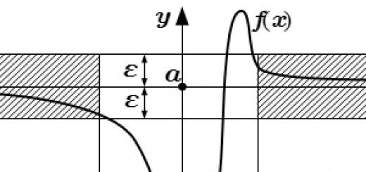
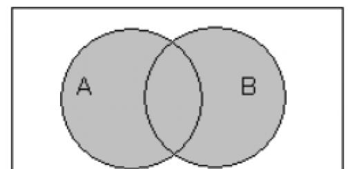
The scheme for measuring the heat flux density is shown in the drawing.
Scheme for measuring the heat flux density
1 - enclosing structure; 2 - heat flux converter; 3 - emf meter;
Temperature of internal and external air; , , - outdoor temperature,
internal surfaces of the enclosing structure near and under the transducer, respectively;
Thermal resistance of the building envelope and heat flux converter;
Heat flux density before and after fixing the transducer.
2. Hardware
2.1. To measure the density of heat fluxes, the ITP-11 device is used (it is allowed to use the previous model of the ITP-7 device) according to the specifications.
The technical characteristics of the ITP-11 device are given in reference Appendix 1.
2.2. During thermal testing of enclosing structures, it is allowed to measure the density of heat fluxes using separately manufactured and calibrated heat flux converters with thermal resistance up to 0.025-0.06 (sq.m) / W and devices that measure the emf generated by the converters.
It is allowed to use the converter used in the installation for determining the thermal conductivity in accordance with GOST 7076-78.
2.3. Heat flow converters according to clause 2.2 must meet the following basic requirements:
materials for the "auxiliary wall" (plate) must retain their physical and mechanical properties at an ambient temperature of 243 to 323 K (from minus 30 to plus 50°C);
materials should not be wetted and moistened with water in liquid and vapor phases;
the ratio of the transducer diameter to its thickness must be at least 10;
converters must have a guard zone located around the thermocouple battery, the linear size of which should be at least 30% of the radius or half of the linear size of the converter;
each manufactured heat flux converter must be calibrated in organizations that, in the prescribed manner, have received the right to produce these converters;
under the above environmental conditions, the calibration characteristics of the transducer must be maintained for at least one year.
2.4. Calibration of transducers according to clause 2.2 is allowed to be carried out on an installation for determining thermal conductivity in accordance with GOST 7076-78, in which the heat flux density is calculated from the results of measuring the temperature difference on reference samples of materials certified in accordance with GOST 8.140-82 and installed instead of the tested samples. The calibration method for the heat flux converter is given in the recommended appendix 2.
2.5. The converters are checked at least once a year, as indicated in paragraphs. 2.3, 2.4.
2.6. To measure emf. heat flux converter, it is allowed to use a portable potentiometer PP-63 according to GOST 9245-79, digital voltammeters V7-21, F30 or other emf meters, in which the calculated error in the region of measured emf. of the heat flux converter does not exceed 1% and the input resistance is at least 10 times higher than the internal resistance of the converter.
In thermal testing of building envelopes using separate transducers, it is preferable to use automatic recording systems and devices.
3.Preparation for measurement
3.1. The measurement of heat flux density is carried out, as a rule, from the inside of the enclosing structures of buildings and structures.
It is allowed to measure the density of heat fluxes from the outside of the enclosing structures if it is impossible to measure them from the inside (aggressive environment, fluctuations in air parameters), provided that a stable temperature on the surface is maintained. The control of heat transfer conditions is carried out using a temperature probe and means for measuring the heat flux density: when measured for 10 minutes, their readings should be within the measurement error of the instruments.
3.2. Surface areas are selected specific or characteristic for the entire tested building envelope, depending on the need to measure the local or average heat flux density.
The areas selected on the enclosing structure for measurements must have a surface layer of the same material, the same processing and surface condition, have the same conditions for radiant heat transfer and should not be in close proximity to elements that can change the direction and value of heat flows.
3.3. The surface areas of the enclosing structures, on which the heat flux converter is installed, are cleaned until the visible and tangible roughnesses are eliminated.
3.4. The transducer is tightly pressed over its entire surface to the enclosing structure and fixed in this position, ensuring constant contact of the heat flux transducer with the surface of the studied areas during all subsequent measurements.
When mounting the transducer between it and the enclosing structure, the formation of air gaps is not allowed. To eliminate them, a thin layer of technical vaseline is applied to the surface area at the measurement sites, covering the surface irregularities.
The transducer can be fixed along its lateral surface using a solution of building gypsum, technical vaseline, plasticine, a rod with a spring, and other means that exclude distortion of the heat flux in the measurement zone.
3.5. During operational measurements of the heat flux density, the loose surface of the transducer is glued with a layer of material or painted over with paint with the same or similar degree of emissivity with a difference of 0.1 as that of the material of the surface layer of the enclosing structure.
3.6. The reading device is located at a distance of 5-8 m from the measurement site or in an adjacent room to eliminate the observer's influence on the heat flux value.
3.7. When using devices for measuring emf, which have restrictions on the ambient temperature, they are placed in a room with an air temperature acceptable for the operation of these devices, and the heat flux converter is connected to them using extension wires.
When measuring with the ITP-1 device, the heat flux converter and the measuring device are located in the same room, regardless of the air temperature in the room.
3.8. The equipment according to clause 3.7 is prepared for operation in accordance with the operating instructions for the corresponding device, including taking into account the necessary exposure time of the device to establish a new temperature regime in it.
4. Taking measurements
4.1. Measurement of heat flux density is carried out:
when using the ITP-11 device - after the restoration of heat transfer conditions in the room near the control sections of the enclosing structures, distorted during preparatory operations, and after the restoration directly on the test site of the previous heat transfer regime that was disturbed when the converter was attached;
during thermal tests using heat flux converters according to clause 2.2 - after the onset of a new steady state of heat transfer under the converter.
After performing the preparatory operations according to paragraphs. 3.2-3.5 when using the ITP-11 device, the heat transfer mode at the measurement site is restored approximately after 5 - 10 minutes, when using the heat flux converters according to clause 2.2 - after 2-6 hours.
The indicator of the completion of the transient heat transfer mode and the possibility of measuring the heat flux density can be considered the repeatability of the results of measuring the heat flux density within the established measurement error.
4.2. When measuring the heat flow in a building envelope with a thermal resistance of less than 0.6 (sq.m) / W, the temperature of its surface is simultaneously measured using thermocouples at a distance of 100 mm from the converter, below it and the temperature of the internal and external air at a distance of 100 mm from the wall .
5. Processing of results
5.1. When using ITP-11 devices, the value of heat flux density (W / sq.m) is obtained directly from the scale of the device.
5.2. When using separate transducers and millivoltmeters to measure emf. the density of the heat flux passing through the converter, , W/sq.m, is calculated by the formula
(1)
5.3. The determination of the calibration coefficient of the transducer, taking into account the test temperature, is carried out according to the recommended Appendix 2.
5.4. The value of the heat flux density, W / sq.m, when measured according to clause 4.3 is calculated by the formula
(2)
|
where - And - |
outside air temperature in front of the converter, K (°С); surface temperature in the measurement area near the transducer and under the transducer, respectively, K (°С). |
5.5. The measurement results are recorded in the form given in the recommended Appendix 3.
5.6. The result of determining the heat flux density is taken as the arithmetic mean of the results of five measurements at one position of the transducer on the building envelope.
Attachment 1
Reference
Technical characteristics of the device ITP-11
The ITP-11 device is a combination of a heat flux converter into an electrical direct current signal with a measuring device, the scale of which is graduated in units of heat flux density.
1. Limits of measurement of heat flux density: 0-50; 0-250 W/sq.m.
2. Price division of the instrument scale: 1; 5 W/sq.m.
3. The main error of the device in percent at an air temperature of 20 °C.
![]()
4. Additional error due to changes in the temperature of the air surrounding the measuring device does not exceed 1% for every 10 K (°C) temperature change in the range from 273 to 323 K (from 0 to 50°C).
Additional error due to temperature change of the heat flux converter does not exceed 0.83% per 10 K (°C) of temperature change in the range from 273 to 243 K (from 0 to minus 30 °C).
5. Thermal resistance of the heat flux converter - no more than 3·10 (kv/m·K)/W.
6. The time for establishing indications is no more than 3.5 minutes.
7. Overall dimensions of the case - 290x175x100 mm.
8. Overall dimensions of the heat flux converter: diameter 27 mm, thickness 1.85 mm.
9. Overall dimensions of the measuring device - 215x115x90 mm.
10 The length of the connecting electrical wire - 7 m.
11. Weight of the device without a case - no more than 2.5 kg.
12. Power supply - 3 elements "316".
Annex 2
Heat flux converter calibration method
The manufactured heat flux converter is subjected to calibration at the installation for determining the thermal conductivity of building materials according to GOST 7076-78, in which a calibrated converter and a reference material sample according to GOST 8.140-82 are installed instead of the test sample.
When calibrating, the space between the temperature control plate of the installation and the reference sample outside the converter must be filled with a material similar in thermophysical properties to the material of the converter in order to ensure the one-dimensionality of the heat flux passing through it in the working section of the installation. E.m.f. measurement on the converter and the reference sample is carried out by one of the devices listed in clause 2.6 of this standard.
The calibration coefficient of the transducer, W / (sq.m mV) at a given average temperature of the experiment is found from the results of measurements of the heat flux density and emf. according to the following ratio
The heat flux density is calculated from the results of measuring the temperature difference on the reference sample according to the formula
|
where |
thermal conductivity of the reference material, W/(m.K); |
|
|
temperature of the upper and lower surfaces of the standard, respectively, K(°С); |
||
|
standard thickness, m |
It is recommended to choose the average temperature in the experiments when calibrating the transducer in the range from 243 to 323 K (from minus 30 to plus 50 °C) and maintain it with a deviation of no more than ±2 K (°C).
The result of determining the coefficient of the transducer is taken as the arithmetic mean of the values calculated from the results of measurements of at least 10 experiments. The number of significant digits in the value of the calibration factor of the transducer is taken in accordance with the measurement error.
The temperature coefficient of the transducer, K (), is found from the results of measurements of the emf. in calibration experiments at various average transducer temperatures according to the ratio
![]() ,
,
|
where , |
Average transducer temperatures in two experiments, K (°C); |
|
Calibration coefficients of the transducer at an average temperature, respectively, and , W/(sq.m V). |
The difference between the average temperatures and must be at least 40 K (°C).
The result of determining the temperature coefficient of the transducer is taken as the arithmetic mean value of the density calculated from the results of at least 10 experiments with different average temperature of the transducer.
The value of the calibration coefficient of the heat flux converter at the test temperature , W / (sq.m mV), is found by the following formula
![]() ,
,
|
where |
(The value of the calibration coefficient of the transducer at the test temperature W/(sq.m.mV) Type and number of measuring device
Operator's signature ___________________ Date of measurements ___________ The text of the document is verified by: official publication Gosstroy of the USSR - M.: Publishing house of standards, 1988 | |||||||||||||||||||||||||||||||||||||||||||||||||||
1 Basic concepts and definitions - temperature field, gradient, heat flux, heat flux density (q, Q), Fourier law.
temperature field– a set of temperature values at all points of the studied space for each moment of time..gif" width="131" height="32 src=">
The amount of heat, W, passing per unit time through an isothermal surface of area F is called heat flow and is determined from the expression: https://pandia.ru/text/78/654/images/image004_12.gif" width="15" height="32">, W/m2, is called heat flux density: .
The relationship between the amount of heat dQ, J, which during the time dt passes through the elementary area dF, located on an isothermal surface, and the temperature gradient dt/dn is established by the Fourier law: .
2. Equation of heat conduction, uniqueness conditions.
The differential equation for heat conduction is derived with the following assumptions:
The body is homogeneous and isotropic;
The physical parameters are constant;
The deformation of the considered volume, associated with a change in temperature, is very small compared to the volume itself;
Internal sources of heat in the body, which in general case can be given as ![]() , are evenly distributed.
, are evenly distributed.
https://pandia.ru/text/78/654/images/image009_5.gif" width="195" height="45 src=">.
The differential equation of heat conduction establishes a relationship between temporal and spatial changes in temperature at any point in the body where the process of heat conduction occurs.
If we take the thermophysical characteristics constant, which was assumed when deriving the equation, then difur takes the form: https://pandia.ru/text/78/654/images/image011_4.gif" width="51" height="44"> - coefficient thermal diffusivity.
And ![]() , where
, where ![]() is the Laplace operator in the Cartesian coordinate system.
is the Laplace operator in the Cartesian coordinate system.
Then ![]() .
.
Uniqueness conditions or boundary conditions include:
geometric terms,
3. Thermal conductivity in the wall (boundary conditions of the 1st kind).
Thermal conductivity of a single-layer wall.
Consider a homogeneous flat wall of thickness d. Temperatures tc1 and tc2 that are constant in time are maintained on the outer surfaces of the wall. The thermal conductivity of the wall material is constant and equal to l.
In the stationary mode, in addition, the temperature changes only in the direction perpendicular to the plane of the stack (axis 0x): ![]() ..gif" width="129" height="47">
..gif" width="129" height="47">
Let us determine the heat flux density through a flat wall. In accordance with the Fourier law, taking into account the equality (*), we can write: .
Consequently ![]() (**).
(**).
The temperature difference in equation (**) is called temperature difference. It can be seen from this equation that the heat flux density q varies in direct proportion to the thermal conductivity l and temperature difference Dt and inversely proportional to the wall thickness d.
The ratio is called the thermal conductivity of the wall, and its reciprocal is https://pandia.ru/text/78/654/images/image023_1.gif" width="213" height="25">.
The thermal conductivity l should be taken at the average wall temperature.
Thermal conductivity of a multilayer wall.
For each layer: ![]() ; ; https://pandia.ru/text/78/654/images/image027_1.gif" width="433" height="87 src=">
; ; https://pandia.ru/text/78/654/images/image027_1.gif" width="433" height="87 src=">
To compare the heat-conducting properties of a multilayer flat wall with the properties of homogeneous materials, the concept is introduced equivalent thermal conductivity. This is the thermal conductivity of a single-layer wall, the thickness of which is equal to the thickness of the multilayer wall under consideration, i.e..gif" width="331" height="52">
Hence we have:
 .
.
4. Heat transfer through a flat wall (boundary conditions of the 3rd kind).
The transfer of heat from one moving medium (liquid or gas) to another through a solid wall of any shape separating them is called heat transfer. The features of the process at the boundaries of the wall during heat transfer are characterized by boundary conditions of the third kind, which are set by the values of the liquid temperature on one and the other side of the wall, as well as the corresponding values of the heat transfer coefficients.
Consider a stationary process of heat transfer through an infinite homogeneous flat wall of thickness d. Thermal conductivity of the wall l, ambient temperatures tl1 and tl2, heat transfer coefficients a1 and a2 are given. It is necessary to find the heat flux from the hot liquid to the cold one and the temperatures on the wall surfaces tc1 and tc2. The heat flux density from the hot medium to the wall is determined by the equation: ![]() . The same heat flux is transferred by heat conduction through a solid wall:
. The same heat flux is transferred by heat conduction through a solid wall: ![]() and from the second wall surface to the cold environment: DIV_ADBLOCK119">
and from the second wall surface to the cold environment: DIV_ADBLOCK119">
Then https://pandia.ru/text/78/654/images/image035_0.gif" width="128" height="75 src="> - heat transfer coefficient, the numerical value k expresses the amount of heat passing through the unit of the wall surface per unit time pr the temperature difference between the hot and cold medium is 1K and has the same unit of measurement as the heat transfer coefficient, J / (s * m2K) or W / (m2K).
The reciprocal of the heat transfer coefficient is called thermal resistance to heat transfer:.
https://pandia.ru/text/78/654/images/image038_0.gif" width="37" height="25"> thermal resistance of thermal conductivity.
For sandwich wall  .
.
Heat flux density through a multilayer wall: ![]() .
.
The heat flux Q, W, passing through a flat wall with a surface area F, is equal to: ![]() .
.
The temperature at the boundary of any two layers under boundary conditions of the third kind can be determined by the equation  . You can also determine the temperature graphically.
5. Thermal conductivity in a cylindrical wall (boundary conditions of the 1st kind).
Let us consider a stationary process of heat conduction through a homogeneous cylindrical wall (pipe) of length l with an inner radius r1 and an outer radius r2. The thermal conductivity of the wall material l is a constant value. Constant temperatures tc1 and tc2 are set on the wall surface.
In the case (l>>r), the isothermal surfaces will be cylindrical, and the temperature field will be one-dimensional. That is, t=f(r), where r is the current coordinate of the cylindrical system, r1£r£r2..gif" width="113" height="48">.
The introduction of a new variable allows us to bring the equation to the form: https://pandia.ru/text/78/654/images/image047.gif" width="107" height="25">, we have:
https://pandia.ru/text/78/654/images/image049.gif" width="253" height="25 src=">.
Substituting the values of C1 and C2 into the equation ![]() , we get:
, we get:
https://pandia.ru/text/78/654/images/image051.gif" width="277" height="25 src=">.
This expression is the equation of a logarithmic curve. Consequently, inside a homogeneous cylindrical wall at a constant value of thermal conductivity, the temperature changes according to a logarithmic law.
To find the amount of heat passing through a cylindrical wall surface area F per unit time, you can use the Fourier law:
Substituting into the equation of the Fourier law the value of the temperature gradient according to the equation ![]() we get:
we get:  (*) ® Q value does not depend on the wall thickness, but on the ratio of its outer diameter to the inner one.
If you refer the heat flux per unit length of the cylindrical wall, then equation (*) can be written as https://pandia.ru/text/78/654/images/image056.gif" width="67" height="52 src="> is the thermal resistance of the thermal conductivity of the cylindrical wall.
For a multilayer cylindrical wall https://pandia.ru/text/78/654/images/image058.gif" width="225" height="57 src=">.
6. Heat transfer through a cylindrical wall (boundary conditions of the 3rd kind).
Consider a uniform cylindrical wall of great length with an inner diameter d1, an outer diameter d2 and a constant thermal conductivity. The temperature values of the hot tl1 and cold tl2 medium and the heat transfer coefficients a1 and a2 are given. for stationary mode, we can write:
https://pandia.ru/text/78/654/images/image060.gif" width="116" height="75 src=">.gif" width="157" height="25 src=">
where  - linear heat transfer coefficient, characterizes the intensity of heat transfer from one liquid to another through the wall separating them; numerically equal to the amount of heat that passes from one medium to another through the wall of a pipe 1 m long per unit time with a temperature difference between them of 1 K.
The reciprocal of the linear heat transfer coefficient is called linear thermal resistance to heat transfer.
For a multilayer wall, the linear thermal resistance to heat transfer is the sum of the linear thermal resistances to heat transfer and the sum of the linear thermal resistances to thermal conductivity of the layers.
Temperatures at the boundary between layers: https://pandia.ru/text/78/654/images/image065.gif" width="145" height="29">;  ; https://pandia.ru/text/78/654/images/image068.gif" width="160" height="25 src=">
where  – heat transfer coefficient for ball wall.
The reciprocal of the heat transfer coefficient of the spherical wall is called thermal resistance to heat transfer of the spherical wall.
Border conditionsI kind.
Let there be a ball with inner and outer surface radii r1 and r2, constant thermal conductivity, and given uniformly distributed surface temperatures tc1 and tc2.
Under these conditions, the temperature depends only on the radius r. According to the Fourier law, the heat flux through the spherical wall is equal to: ![]() .
.
Integration of the equation gives the following temperature distribution in the spherical layer: 
https://pandia.ru/text/78/654/images/image073.gif" width="316" height="108">;
Consequently  , d - wall thickness.
Temperature distribution:  ® at constant thermal conductivity, the temperature in the spherical wall changes according to the hyperbolic law.
8. Thermal resistance.
Single layer flat wall:
Boundary conditions of the 1st kind
The ratio is called the thermal conductivity of the wall, and its reciprocal is https://pandia.ru/text/78/654/images/image036_0.gif" width="349" height="55">.
Single layer cylindrical wall:
Boundary conditions of the 1st kind
Value https://pandia.ru/text/78/654/images/image076.gif" width="147" height="56 src=">)
Boundary conditions of the 3rd kind
Linear thermal resistance to heat transfer: https://pandia.ru/text/78/654/images/image078.gif" width="249" height="53"> (multilayer wall)
9. Critical insulation diameter.
Let us consider the case when the pipe is covered with a single-layer thermal insulation with an outer diameter d3. assuming given and constant heat transfer coefficients a1 and a2, temperatures of both liquids tl1 and tl2, thermal conductivity of the pipe l1 and insulation l2.
According to the equation  , the expression for the linear thermal resistance to heat transfer through a two-layer cylindrical wall has the form: https://pandia.ru/text/78/654/images/image080.gif" width="72" height="52 src="> will increase, and the term decreases.In other words, an increase in the outer diameter of the insulation entails an increase in the thermal resistance to thermal conductivity of the insulation and a decrease in the thermal resistance to heat transfer on its outer surface.The latter is due to an increase in the area of the outer surface.
Function extremum Rl – – critical diameter denoted as dcr. Serves as an indicator of the suitability of the material for use as thermal insulation for a pipe with a given outer diameter d2 at a given heat transfer coefficient a2.
10. Choice of thermal insulation according to the critical diameter.
See question 9. The diameter of the insulation must exceed the critical diameter of the insulation.
11. Heat transfer through a ribbed wall. Finning factor.
Consider a ribbed wall with thickness d and thermal conductivity l. On the smooth side, the surface area is F1, and on the ribbed side, F2. the temperatures tl1 and tl2 constant in time, as well as the heat transfer coefficients a1 and a2, are set.
Let us denote the temperature of a smooth surface as tc1. Let us assume that the temperatures of the surfaces of the fins and the wall itself are the same and equal to tc2. Such an assumption, generally speaking, does not correspond to reality, but it simplifies calculations and is often used.
When tl1 > tl2, the following expressions can be written for the heat flux Q:
![]() ;
;![]() ;https://pandia.ru/text/78/654/images/image086.gif" width="148" height="28 src=">
;https://pandia.ru/text/78/654/images/image086.gif" width="148" height="28 src=">
where  – heat transfer coefficient for ribbed wall.
When calculating the heat flux density per unit of the non-ribbed wall surface, we obtain:  . k1 is the heat transfer coefficient related to the non-finned wall surface.
The ratio of the area of the ribbed surface to the area of the smooth surface F2/F1 is called finning factor.
12. Non-stationary thermal conductivity. Guide point. physical meaning Bi, Fo.
Non-stationary thermal conductivity is a process in which the temperature in given point of a solid body, the set of indicated temperatures changes with time and forms a non-stationary temperature field, the finding of which is the main task of non-stationary heat conduction. The processes of unsteady heat conduction have great importance for heating, ventilation, air conditioning, heat supply and heat generating installations. Enclosures of buildings experience time-varying thermal effects both from the side of the outside air and from the side of the room; thus, the process of non-stationary heat conduction is carried out in the array of the building envelope. The problem of finding a three-dimensional temperature field can be formulated in accordance with the principles outlined in the section "mathematical formulation of heat transfer problems". The formulation of the problem includes the heat conduction equation: , where is the thermal diffusivity m2/s, as well as the uniqueness conditions that make it possible to single out a single solution from the set of solutions of the equation that differ in the value of the integrating constants.
The uniqueness conditions include initial and boundary conditions. The initial conditions set the values of the desired function t at the initial moment of time over the entire region D. As the region D in which it is necessary to find the temperature field, we will consider a rectangular parallelepiped with dimensions 2d, 2ly, 2lz, for example, an element of a building structure. Then the initial conditions can be written as: for t =0 and - d£x£d; - ly£y£ly; -lz£z£lz we have t = t(x, y, z, 0) = t0(x, y, z). It can be seen from this entry that the origin of the Cartesian coordinate system is located at the center of symmetry of the parallelepiped.
We formulate the boundary conditions in the form of boundary conditions of the third kind, which are often encountered in practice. Boundary conditions of the III kind set for any moment of time on the boundaries of the region D the heat transfer coefficient and the ambient temperature. In the general case, these values can be different in different parts of the surface S of the region D. For the case of the same heat transfer coefficient a on the entire surface S and everywhere the same ambient temperature tzh, the boundary conditions of the third kind at t > 0 can be written as: ; ;
where . S is the surface bounding the area D.
The temperature in each of the three equations is taken on the corresponding face of the parallelepiped.
Let us consider the analytical solution of the problem formulated above in the one-dimensional version, i.e., under the condition ly, lz »d. In this case, it is required to find the temperature field of the form t = t(x, t). Let's write the problem statement:
the equation ![]() ;
;
initial condition: at t = 0 we have t(x, 0) = t0 = const;
boundary condition: for x = ±d, t > 0 we have https://pandia.ru/text/78/654/images/image095.gif" width="141" height="27">. The problem is in order to obtain a specific formula t = t(x, t), which makes it possible to find the temperature t at any point of the plate at an arbitrary moment in time.
Let us formulate the problem in dimensionless variables, this will reduce the entries and make the solution more universal. The dimensionless temperature is , the dimensionless coordinate is X = x/d..gif" width="149" height="27 src=">.gif" width="120" height="25">, where – biot number.
The formulation of the problem in a dimensionless form contains a single parameter - the Biot number, which in this case is a criterion, since it is composed only of the quantities included in the uniqueness condition. The use of the Biot number is associated with finding the temperature field in a solid, so the denominator Bi is the thermal conductivity of the solid. Bi is a predetermined parameter and is a criterion.
If we consider 2 processes of non-stationary heat conduction with the same Biot numbers, then, according to the third similarity theorem, these processes are similar. This means that at similar points (i.e. at X1=X2; Fo1=Fo2) the dimensionless temperatures will be numerically equal: Q1=Q2. therefore, having made one calculation in a dimensionless form, we will obtain a result that is valid for a class of similar phenomena that may differ in the dimensional parameters a, l, d, t0 and tl.
13. Non-stationary thermal conductivity for an unlimited flat wall.
See question 12.
17. Equation of energy. conditions for unambiguity.
The energy equation describes the process of heat transfer in material environment. At the same time, its distribution is associated with the transformation into other forms of energy. The law of conservation of energy in relation to the processes of its transformation is formulated in the form of the first law of thermodynamics, which is the basis for the derivation of the energy equation. The medium in which heat propagates is assumed to be continuous; it can be stationary or moving. Since the case of a moving medium is more general, we use the expression for the first law of thermodynamics for the flow: (17.1) , where q is the input heat, J/kg; h is the enthalpy, J/kg; w is the velocity of the medium at the considered point, m/s; g is the free fall acceleration; z is the height at which the considered element of the medium is located, m; ltr is work against internal friction forces, J/kg.
In accordance with equation 17.1, the heat input is spent on increasing the enthalpy, kinematic energy and potential energy in the field of gravity, as well as on doing work against viscous forces..gif" width="265 height=28" height="28"> (17.2) .
T. to. (17.3) .
 Let us calculate the amount of heat input and output per unit time for a medium element in the form of a rectangular parallelepiped, the dimensions of which are small enough to assume a linear change in the heat flux density within its limits..gif" width="236" height="52 ">; their difference is .
Carrying out a similar operation for the 0y and 0z axes, we obtain the differences, respectively: difference we get the resulting amount of heat supplied (or removed) to the element per unit of time.
We restrict ourselves to the case of a flow with a moderate speed, then the amount of heat supplied is equal to the change in enthalpy. If we assume that the elementary parallelepiped is fixed in space and its faces are permeable to the flow, then the indicated ratio can be represented as: https://pandia.ru/text/78/654/images/image114.gif" width="18" height="31"> – rate of change of enthalpy at a fixed point in space enclosed by an elementary parallelepiped; the minus sign is introduced to match the transfer of heat and the change in enthalpy: the resulting influx of heat<0 должен вызывать увеличение энтальпии.
(17.10) .The derivation of the energy equation is completed by substituting expressions (17.6) and (17.10) into equation (17.4). since this operation is of a formal nature, we will carry out transformations only for the 0x axis: ![]() (17.11)
.
(17.11)
.
With constant physical parameters of the medium, we obtain the following expression for the derivative: ![]() (17.12)
. Having received similar expressions for projections on other axes, we will make up of them the sum enclosed in brackets on the right side of equation (17.4). And after some transformations we get energy equation for an incompressible medium at moderate flow rates:
(17.12)
. Having received similar expressions for projections on other axes, we will make up of them the sum enclosed in brackets on the right side of equation (17.4). And after some transformations we get energy equation for an incompressible medium at moderate flow rates:
(17.13) .
The left side of the equation characterizes the rate of temperature change of a moving fluid particle. The right side of the equation is the sum of derivatives of the form and, therefore, determines the resulting supply (or removal) of heat due to heat conduction.
Thus, the energy equation has a clear physical meaning: the change in temperature of a moving individual fluid particle (left side) is determined by the heat inflow into this particle from the fluid surrounding it due to heat conduction (right side).
For a stationary environment, convective members https://pandia.ru/text/78/654/images/image128.gif" width="168" height="51">.gif" width="76" height="20 src= ">.
conditions for unambiguity.
Differential equations have infinite set solutions, this fact is formally reflected in the presence of arbitrary constants of integration. To solve a specific engineering problem, some additional conditions should be added to the equations related to the essence and distinctive features of this problem.
The fields of the desired functions - temperature, velocity and pressure - are found in a certain area, for which the shape and dimensions must be specified, and in a certain time interval. To derive a single solution of the problem from a set of possible ones, it is necessary to set the values of the sought functions: at the initial moment of time in the entire area under consideration; at any time on the boundaries of the area under consideration.
I. Measurement of the density of heat fluxes passing through the building envelope. GOST 25380-82.
Heat flux - the amount of heat transferred through an isothermal surface per unit time. Heat flow is measured in watts or kcal / h (1 W \u003d 0.86 kcal / h). The heat flux per unit of isothermal surface is called the heat flux density or heat load; usually denoted by q, measured in W / m2 or kcal / (m2 × h). The heat flux density is a vector, any component of which is numerically equal to the amount of heat transferred per unit time through a unit area perpendicular to the direction of the taken component.
Measurements of the density of heat fluxes passing through the building envelope are carried out in accordance with GOST 25380-82 "Buildings and structures. Method for measuring the density of heat fluxes passing through the building envelope".
This standard establishes a unified method for determining the density of heat fluxes passing through single-layer and multi-layer building envelopes of residential, public, industrial and agricultural buildings and structures at pilot study and under their operating conditions.
The heat flux density is measured on the scale of a specialized device, which includes a heat flux converter, or is calculated from the results of emf measurement. on pre-calibrated heat flux transducers.
The scheme for measuring the heat flux density is shown in the drawing.
1 - enclosing structure; 2 - heat flow converter; 3 - emf meter;
tv, tn - temperature of internal and external air;
τн, τв, τ"в — the temperature of the outer, inner surfaces of the enclosing structure near and under the converter, respectively;
R1, R2 - thermal resistance of the building envelope and heat flux converter;
q1, q2 are the heat flux density before and after fixing the transducer
II. Infrared radiation. Sources. Protection.
Protection against infrared radiation in the workplace.
The source of infrared radiation (IR) is any heated body, the temperature of which determines the intensity and spectrum of the emitted electromagnetic energy. The wavelength with the maximum energy of thermal radiation is determined by the formula:
λmax = 2.9-103 / T [µm] (1)
where T is the absolute temperature of the radiating body, K.
Infrared radiation is divided into three areas:
shortwave (X = 0.7 - 1.4 microns);
medium wave (k \u003d 1.4 - 3.0 microns):
long-wavelength (k = 3.0 μm - 1.0 mm).
Electric waves of the infrared range mainly have a thermal effect on the human body. In this case, it is necessary to take into account: the intensity and wavelength with maximum energy; radiated surface area; duration of exposure per working day and duration of continuous exposure; intensity of physical labor and air mobility in the workplace; quality of overalls; individual characteristics working.
Rays of the short-wave range with a wavelength of λ ≤ 1.4 μm have the ability to penetrate into the tissue of the human body for several centimeters. Such IR radiation easily penetrates through the skin and skull into the brain tissue and can affect brain cells, causing severe brain damage, the symptoms of which are vomiting, dizziness, dilation of skin blood vessels, a drop in blood pressure, and impaired blood circulation. and breathing, convulsions, sometimes loss of consciousness. When irradiated with short-wave infrared rays, an increase in the temperature of the lungs, kidneys, muscles and other organs is also observed. Specific biologically active substances appear in the blood, lymph, cerebrospinal fluid, metabolic disturbances are observed, and the functional state of the central nervous system changes.
The rays of the medium wave range with a wavelength of λ = 1.4 - 3.0 microns are retained in the surface layers of the skin at a depth of 0.1 - 0.2 mm. Therefore, their physiological effect on the body is manifested mainly in an increase in skin temperature and heating of the body.
The most intense heating of the human skin surface occurs with IR radiation with λ > 3 µm. Under its influence, the activity of the cardiovascular and respiratory systems, as well as the thermal balance of the body, is disrupted, which can lead to heat stroke.
The intensity of thermal radiation is regulated based on subjective feeling human irradiation energy. According to GOST 12.1.005-88, the intensity of thermal exposure of workers from heated surfaces of technological equipment and lighting fixtures should not exceed: 35 W / m2 with exposure to more than 50% of the body surface; 70 W/m2 when exposed to 25 to 50% of the body surface; 100 W/m2 when irradiating no more than 25% of the body surface. From open sources (heated metal and glass, open flame), the intensity of thermal exposure should not exceed 140 W / m2 with exposure of no more than 25% of the body surface and the mandatory use of personal protective equipment, including face protection and eye.
The standards also limit the temperature of the heated surfaces of the equipment in the working area, which should not exceed 45 °C.
The surface temperature of the equipment, inside which the temperature is close to 100 0C, should not exceed 35 0C.
q = 0.78 x S x (T4 x 10-8 - 110) / r2 [W/m2] (2)
The main types of protection against infrared radiation include:
1. time protection;
2. distance protection;
3. shielding, thermal insulation or cooling of hot surfaces;
4. increase in heat transfer of the human body;
5. personal protective equipment;
6. elimination of heat source.
Time protection provides for limiting the time spent by the radiation operating in the area of radiation. The safe time of a person's stay in the zone of action of IR radiation depends on its intensity (flux density) and is determined according to Table 1.
Table 1
Time of safe stay of people in the IR radiation zone
The safe distance is determined by formula (2) depending on the duration of stay in the working area and the allowable density of IR radiation.
The power of IR radiation can be reduced by design and technological solutions (replacement of the mode and method of heating products, etc.), as well as by coating the heating surfaces with heat-insulating materials.
There are three types of screens:
opaque;
· transparent;
translucent.
In opaque screens, energy electromagnetic oscillations, interacting with the substance of the screen, turns into thermal. In this case, the screen heats up and, like any heated body, becomes a source of thermal radiation. The radiation of the screen surface opposite to the source is conditionally considered as the transmitted radiation of the source. Opaque screens include: metal, alpha (from aluminum foil), porous (foam concrete, foam glass, expanded clay, pumice), asbestos and others.
In transparent screens, radiation propagates inside them according to the laws of geometric optics, which ensures visibility through the screen. These screens are made of various types of glass, film water curtains (free and flowing down the glass) are also used.
Translucent screens combine the properties of transparent and non-transparent screens. These include metal meshes, chain curtains, glass screens reinforced with metal mesh.
· heat-reflecting;
· heat-absorbing;
heat dissipative.
This division is rather arbitrary, since each screen has the ability to reflect, absorb and remove heat. The assignment of the screen to one or another group is determined by which of its abilities is more pronounced.
Heat-reflecting screens have a low degree of surface blackness, as a result of which they reflect a significant part of the radiant energy incident on them in the opposite direction. Alfol, sheet aluminum, galvanized steel are used as heat-reflecting materials.
Heat-absorbing screens are called screens made of materials with high thermal resistance (low thermal conductivity). Refractory and heat-insulating bricks, asbestos, and slag wool are used as heat-absorbing materials.
As heat-removing screens, water curtains are most widely used, freely falling in the form of a film, or irrigating another screening surface (for example, metal), or enclosed in a special casing made of glass or metal.
E \u003d (q - q3) / q (3)
E \u003d (t - t3) / t (4)
q3 is the flux density of IR radiation with the use of protection, W/m2;
t is the temperature of IR radiation without the use of protection, °С;
t3 is the temperature of IR radiation with the use of protection, °С.
The air flow directed directly at the worker allows to increase the removal of heat from his body in environment. The choice of air flow rate depends on the severity of the work performed and the intensity of the infrared radiation, but it should not exceed 5 m / s, since in this case the worker experiences discomfort (for example, tinnitus). The effectiveness of air showers increases when the air sent to the workplace is cooled or when finely sprayed water is mixed into it (water-air shower).
As personal protective equipment, overalls made of cotton and woolen fabrics, fabrics with a metal coating (reflecting up to 90% of IR radiation) are used. Goggles, shields with special glasses are designed to protect the eyes - light filters of yellow-green or blue color.
Therapeutic and preventive measures provide for the organization of a rational regime of work and rest. The duration of breaks in work and their frequency are determined by the intensity of IR radiation and the severity of the work. Along with periodic inspections, medical examinations are carried out to prevent occupational diseases.
III. Instruments used.
To measure the density of heat fluxes passing through the building envelope and to check the properties of heat shields, our specialists developed devices of the series.

Application area:
Devices of the IPP-2 series found wide application in construction, scientific organizations, at various energy facilities and in many other industries.
The measurement of heat flux density, as an indicator of the thermal insulation properties of various materials, is carried out using IPP-2 series devices at:
Testing of enclosing structures;
Determination of heat losses in water heating networks;
Carrying out laboratory work in universities (departments "Life Safety", "Industrial Ecology", etc.).


The figure shows a prototype stand "Determining the parameters of the air in the working area and protection from thermal effects" BZhZ 3 (manufactured by Intos + LLC).
The stand contains a source of thermal radiation in the form of a household reflector, in front of which a heat shield made of various materials (fabric, metal sheet, a set of chains, etc.) is installed. Behind the screen at various distances from it inside the room model, the IPP-2 device is placed, which measures the heat flux density. An exhaust hood with a fan is placed above the room model. Measuring device IPP-2 has an additional sensor that allows you to measure the air temperature inside the room. Thus, the stand BZhZ 3 makes it possible to quantify the effectiveness of various types of thermal protection and a local ventilation system.
The stand makes it possible to measure the intensity of thermal radiation depending on the distance to the source, to determine the effectiveness of the protective properties of screens made of various materials.

IV. Principle of operation and design of the IPP-2 device.
Structurally, the measuring unit of the device is made in a plastic case.
The principle of operation of the device is based on measuring the temperature difference on the "auxiliary wall". The magnitude of the temperature difference is proportional to the heat flux density. The temperature difference is measured using a tape thermocouple located inside the probe plate, which acts as an "auxiliary wall".
In the operating mode, the device performs a cyclic measurement of the selected parameter. A transition is made between the modes of measuring the heat flux density and temperature, as well as indicating the battery charge in percentages of 0% ... 100%. When switching between modes, the corresponding inscription of the selected mode is displayed on the indicator. The device can also perform periodic automatic recording of measured values in non-volatile memory with reference to time. Enabling/disabling the recording of statistics, setting the recording parameters, reading the accumulated data is carried out using the software supplied by order.
Peculiarities:
- Possibility to set thresholds for sound and light alarms. Thresholds are the upper or lower limits of the allowable change in the corresponding value. If the upper or lower threshold value is violated, the device detects this event and the LED lights up on the indicator. If the device is configured appropriately, violation of the thresholds is accompanied by an audible signal.
· Transfer of the measured values to the computer on the RS 232 interface.
The advantage of the device is the ability to alternately connect up to 8 different heat flow probes to the device. Each probe (sensor) has its own individual calibration factor (conversion factor Kq), showing how much the voltage from the sensor changes relative to the heat flux. This coefficient is used by the instrument to construct the probe calibration characteristic, which is used to determine the current measured value of the heat flux.
Modifications of probes for measuring heat flux density:
Heat flux probes are designed to measure the surface heat flux density according to GOST 25380-92.
Appearance of heat flow probes

1. PTP-ХХХП press-type heat flux probe with spring is available in the following modifications (depending on the range of heat flux density measurement):
— PTP-2.0P: from 10 to 2000 W/m2;
— PTP-9.9P: from 10 to 9999 W/m2.

2. Heat flow probe in the form of a "coin" on a flexible cable PTP-2.0.
Heat flux density measurement range: from 10 to 2000 W/m2.
Temperature probe modifications:
Appearance of temperature probes

1. Immersion thermocouples TPP-A-D-L based on Pt1000 thermistor (resistance thermocouples) and thermocouples ТХА-А-D-L based on XА thermocouples (electrical thermocouples) are designed to measure the temperature of various liquid and gaseous media, as well as bulk materials.
Temperature measurement range:
- for Chamber of Commerce and Industry-A-D-L: from -50 to +150 °С;
- for ТХА-А-D-L: from -40 to +450 °С.
Dimensions:
- D (diameter): 4, 6 or 8 mm;
- L (length): from 200 to 1000 mm.

2. Thermocouple ТХА-А-D1/D2-LП based on XА thermocouple (electrical thermocouple) is designed to measure the temperature of a flat surface.
Dimensions:
- D1 (diameter of the "metal pin"): 3 mm;
- D2 (base diameter - "patch"): 8 mm;
- L (length of the "metal pin"): 150 mm.

3. Thermocouple ТХА-А-D-LC based on thermocouple ХА (electrical thermocouple) is designed to measure the temperature of cylindrical surfaces.
Temperature measurement range: from -40 to +450 °С.
Dimensions:
- D (diameter) - 4 mm;
- L (length of the "metal pin"): 180 mm;
- tape width - 6 mm.

The delivery set of the device for measuring the density of the thermal load of the medium includes:
2. Probe for measuring heat flux density.*
3. Temperature probe.*
4. Software.**
5. Cable for connecting to a personal computer. **
6. Certificate of calibration.
7. Operation manual and passport for the IPP-2 device.
8. Passport for thermoelectric converters (temperature probes).
9. Passport for the heat flux density probe.
10. Network adapter.
* - Measuring ranges and probe design are determined at the order stage
** - Positions are delivered by special order.
V. Preparing the device for operation and taking measurements.
Preparing the device for work.
Remove the device from the packaging. If the device is brought into a warm room from a cold one, it is necessary to let the device warm up to room temperature for 2 hours. Fully charge the battery within four hours. Place the probe in the place where measurements will be taken. Connect the probe to the instrument. If the device is to be operated in combination with a personal computer, it is necessary to connect the device to a free COM port of the computer using a connecting cable. Connect the network adapter to the device and install the software according to the description. Turn on the device by briefly pressing the button. If necessary, adjust the device in accordance with paragraph 2.4.6. Operation manuals. When working with a personal computer, set the network address and exchange rate of the device in accordance with paragraph 2.4.8. Operation manuals. Start measuring.
Below is a diagram of switching in the "Work" mode.

Preparation and carrying out measurements during thermal testing of building envelopes.
1. The measurement of heat flux density is carried out, as a rule, from the inside of the enclosing structures of buildings and structures.
It is allowed to measure the density of heat fluxes from the outside of the enclosing structures if it is impossible to measure them from the inside (aggressive environment, fluctuations in air parameters), provided that a stable temperature on the surface is maintained. The control of heat transfer conditions is carried out using a temperature probe and means for measuring the heat flux density: when measuring for 10 minutes. their readings must be within the measurement error of the instruments.
2. Surface areas are selected specific or characteristic for the entire tested building envelope, depending on the need to measure the local or average heat flux density.
The areas selected on the enclosing structure for measurements must have a surface layer of the same material, the same processing and surface condition, have the same conditions for radiant heat transfer and should not be in close proximity to elements that can change the direction and value of heat flows.
3. The surface areas of the enclosing structures, on which the heat flux converter is installed, are cleaned until the roughness visible and tangible to the touch is eliminated.
4. The transducer is pressed tightly over its entire surface to the enclosing structure and fixed in this position, ensuring constant contact of the heat flux transducer with the surface of the studied areas during all subsequent measurements.
When mounting the transducer between it and the enclosing structure, the formation of air gaps is not allowed. To eliminate them, a thin layer of technical vaseline is applied to the surface area at the measurement sites, covering the surface irregularities.
The transducer can be fixed along its lateral surface using a solution of building gypsum, technical vaseline, plasticine, a rod with a spring, and other means that exclude distortion of the heat flux in the measurement zone.
5. During operational measurements of the heat flux density, the loose surface of the transducer is glued with a layer of material or painted over with paint with the same or similar degree of emissivity with a difference of 0.1 as that of the material of the surface layer of the enclosing structure.
6. The reading device is located at a distance of 5-8 m from the measurement site or in an adjacent room to exclude the influence of the observer on the value of the heat flux.
7. When using devices for measuring emf, which have restrictions on the ambient temperature, they are placed in a room with an air temperature acceptable for the operation of these devices, and the heat flux converter is connected to them using extension wires.
8. The equipment according to claim 7 is prepared for operation in accordance with the operating instructions for the corresponding device, including taking into account the necessary exposure time of the device to establish a new temperature regime in it.
Preparing and taking measurements
(during laboratory work on the example laboratory work"Investigation of means of protection against infrared radiation").
Connect the IR source to the socket. Turn on the IR source ( upper part) and a heat flux density meter IPP-2.
Install the head of the heat flux density meter at a distance of 100 mm from the IR radiation source and determine the heat flux density (average value of three to four measurements).
Manually move the tripod along the ruler, setting the measuring head at the distances from the radiation source indicated in the form of Table 1, and repeat the measurements. Enter the measurement data in the form of table 1.
Construct a graph of the dependence of the IR flux density on the distance.
Repeat measurements according to paragraphs. 1 - 3 with different Data of measurements to enter in the form of a table 1. Construct graphs of the dependence of the flux density of IR radiation on the distance for each screen.
Table form 1
Evaluate the effectiveness of the protective action of the screens according to the formula (3).
Install a protective screen (as directed by the teacher), place a wide brush of the vacuum cleaner on it. Turn on the vacuum cleaner in the air intake mode, simulating an exhaust ventilation device, and after 2-3 minutes (after the screen thermal regime is established), determine the intensity of thermal radiation at the same distances as in paragraph 3. Evaluate the effectiveness of the combined thermal protection using the formula (3).
The dependence of the intensity of thermal radiation on the distance for a given screen in the exhaust ventilation mode should be plotted on the general graph (see item 5).
Determine the effectiveness of protection by measuring the temperature for a given screen with and without exhaust ventilation using formula (4).
Construct graphs of the effectiveness of the protection of exhaust ventilation and without it.
Switch the vacuum cleaner to blower mode and turn it on. By directing the air flow to the surface of a given protective screen (showering mode), repeat the measurements in accordance with paragraphs. 7 - 10. Compare the measurement results of paragraphs. 7-10.
Fix the hose of the vacuum cleaner on one of the racks and turn on the vacuum cleaner in the "blower" mode, directing the air flow almost perpendicular to the heat flow (slightly towards) - an imitation of an air curtain. Using the IPP-2 meter, measure the temperature of the infrared radiation without and with the "blower".
Construct graphs of the "blower" protection efficiency according to the formula (4).
VI. Measurement results and their interpretation
(on the example of laboratory work on the topic "Research of means of protection against infrared radiation" in one of the technical universities in Moscow).
Table. Electrofireplace EXP-1,0/220. Rack for placing interchangeable screens. Rack for installation of a measuring head. Heat flux density meter IPP-2M. Ruler. Vacuum cleaner Typhoon-1200.
The intensity (flux density) of IR radiation q is determined by the formula:
q = 0.78 x S x (T4 x 10-8 - 110) / r2 [W/m2]
where S is the area of the radiating surface, m2;
T is the temperature of the radiating surface, K;
r is the distance from the radiation source, m.
One of the most common types of protection against IR radiation is the shielding of emitting surfaces.
There are three types of screens:
opaque;
· transparent;
translucent.
According to the principle of operation, the screens are divided into:
· heat-reflecting;
· heat-absorbing;
heat dissipative.
Table 1
The effectiveness of protection against thermal radiation with the help of screens E is determined by the formulas:
E \u003d (q - q3) / q
where q is the IR radiation flux density without protection, W/m2;
q3 is the density of the IR radiation flux with the use of protection, W/m2.
Types of protective screens (opaque):
1. Screen mixed - chain mail.
E mail = (1550 - 560) / 1550 = 0.63
2. Metal screen with a blackened surface.
E al+cover = (1550 - 210) / 1550 = 0.86
3. Heat-reflecting aluminum screen.
E al \u003d (1550 - 10) / 1550 \u003d 0.99
Let's plot the dependence of the IR flux density on the distance for each screen.
| No protection |
As we can see, the effectiveness of the protective action of the screens varies:
1. The minimum protective effect of a mixed screen - chain mail - 0.63;
2. Aluminum screen with a blackened surface - 0.86;
3. The heat-reflecting aluminum screen has the greatest protective effect - 0.99.
When assessing the thermal performance of building envelopes and structures and establishing real heat consumption through external building envelopes, the following main regulatory documents are used:
· GOST 25380-82. A method for measuring the density of heat fluxes passing through building envelopes.
When evaluating the thermal performance of various means of protection against infrared radiation, the following main regulatory documents are used:
· GOST 12.1.005-88. SSBT. Work area air. General sanitary and hygienic requirements.
· GOST 12.4.123-83. SSBT. Means of protection against infrared radiation. Classification. General technical requirements.
· GOST 12.4.123-83 “System of labor safety standards. Means of collective protection against infrared radiation. General technical requirements".
20.03.2014
Measurement of the density of heat fluxes passing through the building envelope. GOST 25380-82
Heat flux - the amount of heat transferred through an isothermal surface per unit time. Heat flow is measured in watts or kcal / h (1 W \u003d 0.86 kcal / h). The heat flux per unit of isothermal surface is called the heat flux density or heat load; usually denoted by q, measured in W / m 2 or kcal / (m 2 × h). The heat flux density is a vector, any component of which is numerically equal to the amount of heat transferred per unit time through a unit area perpendicular to the direction of the taken component.
Measurements of the density of heat fluxes passing through the building envelope are carried out in accordance with GOST 25380-82 “Buildings and structures. Method for measuring the density of heat fluxes passing through the building envelope”.
This GOST establishes a method for measuring the density of heat flux passing through single-layer and multi-layer enclosing structures of buildings and structures - public, residential, agricultural and industrial.
Currently, in the construction, acceptance and operation of buildings, as well as in the housing and communal sector great attention pay attention to the quality of the completed construction and interior decoration, thermal insulation of residential buildings, as well as energy savings.
An important evaluation parameter in this case is the heat consumption from insulating structures. Tests of the quality of thermal protection of building envelopes can be performed at different stages: during the commissioning of buildings, at completed construction sites, during construction, during the overhaul of structures, and during the operation of buildings to draw up energy passports of buildings, and on complaints.
Heat flux density measurements should be carried out at an ambient temperature of -30 to +50°C and a relative humidity of not more than 85%.
Measurements of the heat flux density make it possible to estimate the heat flow through the building envelope and, thereby, to determine the thermal performance of the building and construction building envelopes.
This standard is not applicable to assess the thermal performance of enclosing structures that transmit light (glass, plastic, etc.).
Let us consider what the method of measuring the heat flux density is based on. A plate (the so-called "auxiliary wall") is installed on the enclosing structure of the building (structure). The temperature difference formed on this “auxiliary wall” is proportional to its density in the direction of the heat flow. The temperature difference is converted into the electromotive force of thermocouple batteries, which are located on the "auxiliary wall" and are oriented parallel to the heat flow, and are connected in series according to the generated signal. Together, the “auxiliary wall” and the thermocouple stack constitute a measuring transducer for measuring the heat flux density.
Based on the results of measuring the electromotive force of thermocouple batteries, the heat flux density on pre-calibrated transducers is calculated.
The scheme for measuring the heat flux density is shown in the drawing.
1 - enclosing structure; 2 - heat flux converter; 3 - emf meter;
t in, t n- temperature of internal and external air;
τ n, τ in, τ’ in- temperature of the outer and inner surfaces of the enclosing structure near and under the converter, respectively;
R 1 , R 2 - thermal resistance of the building envelope and heat flux converter;
q 1 , q 2- heat flux density before and after fixing the converter
Sources of infrared radiation. Infrared protection in workplaces
The source of infrared radiation (IR) is any heated body, the temperature of which determines the intensity and spectrum of the emitted electromagnetic energy. The wavelength with the maximum energy of thermal radiation is determined by the formula:
λ max = 2.9-103 / T [µm] (1)
where T is the absolute temperature of the radiating body, K.
Infrared radiation is divided into three areas:
- shortwave (X \u003d 0.7 - 1.4 microns);
- medium wave (k \u003d 1.4 - 3.0 microns):
- long-wavelength (k = 3.0 μm - 1.0 mm).
On the human body, electric waves in the IR range mainly have a thermal effect. When evaluating this impact, the following is taken into account:
length and intensity of the wave with maximum energy;
the area of the emitted surface;
duration of exposure during the working day;
duration of continuous exposure;
the intensity of physical labor;
the intensity of air movement in the workplace;
The type of fabric from which the overalls are made;
individual characteristics of the body.
The shortwave range includes rays with a wavelength λ ≤ 1.4 μm. They are characterized by the ability to penetrate into the tissues of the human body to a depth of several centimeters. This impact causes severe damage various bodies and human tissues with aggravating consequences. There is an increase in the temperature of muscle, lung and other tissues. Specific biologically active substances are formed in the circulatory and lymphatic systems. The work of the central nervous system is disrupted.
The medium wave range includes rays with a wavelength λ = 1.4 - 3.0 μm. They penetrate only into the superficial layers of the skin, and therefore their effect on the human body is limited to an increase in the temperature of exposed skin areas and an increase in body temperature.
Long-wavelength range - rays with a wavelength λ > 3 μm. Influencing the human body, they cause the strongest temperature increase in exposed skin areas, which disrupts the activity of the respiratory and cardiovascular systems and disrupts the thermal balance of orgasm, leading to heat stroke.
According to GOST 12.1.005-88, the intensity of thermal exposure of workers from heated surfaces of technological equipment and lighting devices should not exceed: 35 W / m 2 when irradiating more than 50% of the body surface; 70 W/m 2 when exposed to 25 to 50% of the body surface; 100 W / m 2 with irradiation of not more than 25%> of the body surface. From open sources (heated metal and glass, open flame), the intensity of thermal radiation should not exceed 140 W / m 2 with exposure of no more than 25% of the body surface and the mandatory use of personal protective equipment, including face and eye protection.
The standards also limit the temperature of the heated surfaces of the equipment in the working area, which should not exceed 45 °C.
The surface temperature of the equipment, inside which the temperature is close to 100 °C, should not exceed 35 °C.
The main types of protection against infrared radiation include:
1. time protection;
2. distance protection;
3. shielding, thermal insulation or cooling of hot surfaces;
4. increase in heat transfer of the human body;
5. personal protective equipment;
6. elimination of heat source.
There are three types of screens:
opaque;
· transparent;
translucent.
In opaque screens, when the energy of electromagnetic oscillations interacts with the substance of the screen, it is converted into thermal energy. As a result of this transformation, the screen heats up and it itself becomes a source of thermal radiation. Radiation by the screen surface opposite to the source is conventionally considered as transmitted radiation from the source. It becomes possible to calculate the density of the heat flux passing through the unit area of the screen.
With transparent screens, things are different. The radiation falling on the surface of the screen is distributed inside it according to the laws of geometric optics. This explains its optical transparency.
Translucent screens have both transparent and opaque properties.
· heat-reflecting;
· heat-absorbing;
heat dissipative.
In fact, all screens, to one degree or another, have the property of absorbing, reflecting, or dissipating heat. Therefore, the definition of the screen to a particular group depends on which property is most strongly expressed.
Heat-reflecting screens are distinguished by a low degree of blackness of the surface. Therefore, they reflect most of the rays falling on them.
Heat-absorbing screens include screens in which the material from which they are made has a low coefficient of thermal conductivity (high thermal resistance).
Transparent films or water curtains act as heat-removing screens. Screens inside glass or metal protective contours can also be used.
E \u003d (q - q 3) / q (3)
E \u003d (t - t 3) / t (4)
q 3 - flux density of IR radiation with the use of protection, W / m 2;
t is the temperature of IR radiation without the use of protection, °С;
t 3 - temperature of IR radiation with the use of protection, ° С.
Instrumentation Used
To measure the density of heat fluxes passing through the building envelope and to check the properties of heat shields, our specialists developed devices of the series.
Heat flux density measurement range: from 10 to 250, 500, 2000, 9999 W/m2

Application area:
· construction;
objects of energy;
· Scientific research and etc.
The measurement of the heat flux density, as an indicator of the thermal insulation properties of various materials, is carried out by devices of the series at:
· thermotechnical tests of enclosing structures;


determination of heat losses in water heating networks;

conducting laboratory work in universities (departments "Life Safety", "Industrial Ecology", etc.).


The figure shows a prototype stand "Determining the parameters of the air in the working area and protection from thermal effects" BZhZ 3 (manufactured by Intos + LLC).
On the stand there is a source of thermal radiation (household reflector). Screens made of different materials (metal, fabric, etc.) are placed in front of the source. The device is placed behind the screen inside the room model at various distances from the screen. An exhaust hood with a fan is fixed above the room model. The device, in addition to the probe for measuring the heat flux density, is equipped with a probe for measuring the air temperature inside the model. In general, the stand is a visual model for evaluating the effectiveness of various types of thermal protection and a local ventilation system.
With the help of the stand, the effectiveness of the protective properties of screens is determined depending on the materials from which they are made and on the distance from the screen to the source of thermal radiation.
The principle of operation and design of the device IPP-2
Structurally, the device is made in a plastic case. On the front panel of the device there are a four-digit LED indicator, control buttons; on the side surface there are connectors for connecting the device to a computer and a network adapter. On the top panel there is a connector for connecting the primary converter.

Appearance of the device
1 - Battery Status LED
2 - Threshold violation LED indication
3 - Measurement value indicator
4 - Connector for measuring probe
5 , 6 - Control buttons
7 - Connector for connecting to a computer
8 - Connector for network adapter
Principle of operation
The principle of operation of the device is based on measuring the temperature difference on the “auxiliary wall”. The magnitude of the temperature difference is proportional to the heat flux density. The measurement of the temperature difference is carried out using a tape thermocouple located inside the probe plate, which acts as an “auxiliary wall”.
Indication of measurements and operating modes of the device
The device interrogates the measuring probe, calculates the heat flux density and displays its value on the LED indicator. The probe polling interval is about one second.
Registration of measurements
The data received from the measuring probe is written to the unit's non-volatile memory with a certain period. Setting the period, reading and viewing data is carried out using the software.
Communication interface
With the help of a digital interface, the current temperature measurement values, accumulated measurement data can be read from the device, the device settings can be changed. The measuring unit can work with a computer or other controllers via the RS-232 digital interface. The exchange rate via the RS-232 interface is configurable by the user in the range from 1200 to 9600 bps.
Device features:
- the ability to set thresholds for sound and light alarms;
- transfer of measured values to a computer via RS-232 interface.
The advantage of the device is the ability to alternately connect up to 8 different heat flow probes to the device. Each probe (sensor) has its own individual calibration factor (conversion factor Kq), showing how much the voltage from the sensor changes relative to the heat flux. This coefficient is used by the instrument to construct the calibration characteristic of the probe, which determines the current measured value of the heat flux.
Modifications of probes for measuring heat flux density:
Heat flux probes are designed to measure the surface heat flux density according to GOST 25380-92.
Appearance of heat flow probes
1. PTP-ХХХП press-type heat flux probe with spring is available in the following modifications (depending on the range of heat flux density measurement):
PTP-2.0P: from 10 to 2000 W / m 2;
PTP-9.9P: from 10 to 9999 W / m 2.


2. Heat flow probe in the form of a "coin" on a flexible cable PTP-2.0.
Measurement range of heat flux density: from 10 to 2000 W/m 2 .


Temperature probe modifications:
Appearance of temperature probes
1. Immersion thermocouples TPP-A-D-L based on Pt1000 thermistor (resistance thermocouples) and thermocouples ТХА-А-D-L based on XА thermocouples (electrical thermocouples) are designed to measure the temperature of various liquid and gaseous media, as well as bulk materials.
Temperature measurement range:
For CCI-A-D-L: from -50 to +150 °С;
For THA-A-D-L: from -40 to +450 °C.
Dimensions:
D (diameter): 4, 6 or 8 mm;
L (length): from 200 to 1000 mm.


2. Thermocouple ТХА-А-D1/D2-LП based on thermocouple ХА (electrical thermocouple) is designed to measure the temperature of a flat surface.
Dimensions:
D1 (diameter of the "metal pin"): 3 mm;
D2 (base diameter - "patch"): 8 mm;
L (length of "metal pin"): 150 mm.

3. Thermocouple ТХА-А-D-LC based on thermocouple ХА (electrical thermocouple) is designed to measure the temperature of cylindrical surfaces.
Temperature measurement range: from -40 to +450 °С.
Dimensions:
D (diameter) - 4 mm;
L (length of "metal pin"): 180 mm;
Tape width - 6 mm.


The delivery set of the device for measuring the density of the thermal load of the medium includes:
1. Heat flux density meter (measuring unit).

2. Probe for measuring heat flux density.*
3. Temperature probe.*
4. Software.**
5. Cable for connecting to a personal computer. **
6. Certificate of calibration.
7. Operation manual and passport for the device.
8. Passport for thermoelectric converters (temperature probes).
9. Passport for the heat flux density probe.
10. Network adapter.
* – Measuring ranges and probe design are determined at the order stage
** – Items are supplied by special order.
Preparing the instrument for operation and taking measurements
1. Remove the device from the packaging. If the device is brought into a warm room from a cold one, it is necessary to allow the device to warm up to room temperature for at least 2 hours.
2. Charge the batteries by connecting the AC adapter to the device. Charging time for a fully discharged battery is at least 4 hours. In order to increase the service life battery it is recommended to carry out a full discharge once a month until the device automatically turns off, followed by a full charge.
3. Connect measuring unit and measuring probe with connecting cable.
4. When completing the device with a disk with software, install it on a computer. Connect the device to a free COM port of the computer with appropriate connecting cables.
5. Turn on the device by briefly pressing the "Select" button.
6. When the device is turned on, a self-test of the device is carried out for 5 seconds. In the presence of internal malfunctions, the device on the indicator signals the number of the malfunction, accompanied by an audible signal. After successful testing and completion of the download, the indicator displays the current value of the heat flux density. Explanation of test failures and other errors in the operation of the device is given in the section 6 of this instruction manual.
7. After use, turn off the device by briefly pressing the "Select" button.
8. If the device is to be stored for a long time (more than 3 months), the batteries should be removed from the battery compartment.
Below is a diagram of switching in the “Operation” mode.

Preparation and carrying out measurements during thermal testing of building envelopes.
1. The measurement of heat flux density is carried out, as a rule, from the inside of the enclosing structures of buildings and structures.
It is allowed to measure the density of heat fluxes from the outside of the enclosing structures if it is impossible to measure them from the inside (aggressive environment, fluctuations in air parameters), provided that a stable temperature on the surface is maintained. The control of heat transfer conditions is carried out using a temperature probe and means for measuring the heat flux density: when measuring for 10 minutes. their readings must be within the measurement error of the instruments.
2. Surface areas are selected specific or characteristic for the entire tested building envelope, depending on the need to measure the local or average heat flux density.
The areas selected on the enclosing structure for measurements must have a surface layer of the same material, the same processing and surface condition, have the same conditions for radiant heat transfer and should not be in close proximity to elements that can change the direction and value of heat flows.
3. The surface areas of the enclosing structures, on which the heat flux converter is installed, are cleaned until the roughness visible and tangible to the touch is eliminated.
4. The transducer is pressed tightly over its entire surface to the enclosing structure and fixed in this position, ensuring constant contact of the heat flux transducer with the surface of the studied areas during all subsequent measurements.
When mounting the transducer between it and the enclosing structure, the formation of air gaps is not allowed. To eliminate them, a thin layer of technical vaseline is applied to the surface area at the measurement sites, covering the surface irregularities.
The transducer can be fixed along its lateral surface using a solution of building gypsum, technical vaseline, plasticine, a rod with a spring, and other means that exclude distortion of the heat flux in the measurement zone.
5. During operational measurements of the heat flux density, the loose surface of the transducer is glued with a layer of material or painted over with paint with the same or similar degree of emissivity with a difference of Δε ≤ 0.1, as the material of the surface layer of the enclosing structure.
6. The reading device is located at a distance of 5-8 m from the measurement site or in an adjacent room to exclude the influence of the observer on the value of the heat flux.
7. When using devices for measuring emf, which have restrictions on the ambient temperature, they are placed in a room with an air temperature acceptable for the operation of these devices, and the heat flux converter is connected to them using extension wires.
8. The equipment according to claim 7 is prepared for operation in accordance with the operating instructions for the corresponding device, including taking into account the necessary exposure time of the device to establish a new temperature regime in it.
Preparing and taking measurements
(during laboratory work on the example of the laboratory work “Investigation of means of protection against infrared radiation”)
Connect the IR source to the socket. Turn on the IR radiation source (upper part) and the IPP-2 heat flux density meter.
Install the head of the heat flux density meter at a distance of 100 mm from the IR radiation source and determine the heat flux density (the average value of three to four measurements).
Manually move the tripod along the ruler, setting the measuring head at the distances from the radiation source indicated in the form of Table 1, and repeat the measurements. Enter the measurement data in the form of table 1.
Construct a graph of the dependence of the IR flux density on the distance.
Repeat measurements according to paragraphs. 1 - 3 with various protective screens (heat-reflecting aluminum, heat-absorbing fabric, metal with a blackened surface, mixed - chain mail). Enter the measurement data in the form of a table 1. Construct graphs of the dependence of the IR radiation flux density on the distance for each screen.
Table form 1
Estimate the effectiveness of the protective action of the screens according to the formula (3).
Install a protective screen (as directed by the teacher), place a wide brush of the vacuum cleaner on it. Turn on the vacuum cleaner in the air intake mode, simulating an exhaust ventilation device, and after 2-3 minutes (after the screen thermal regime is established), determine the intensity of thermal radiation at the same distances as in paragraph 3. Evaluate the effectiveness of the combined thermal protection using the formula (3 ).
The dependence of the intensity of thermal radiation on the distance for a given screen in the exhaust ventilation mode should be plotted on the general graph (see item 5).
Determine the effectiveness of protection by measuring the temperature for a given screen with and without exhaust ventilation using formula (4).
Construct graphs of the efficiency of protection of exhaust ventilation and without it.
Switch the vacuum cleaner to blower mode and turn it on. By directing the air flow to the surface of a given protective screen (showering mode), repeat the measurements in accordance with paragraphs. 7 - 10. Compare the measurement results of paragraphs. 7-10.
Fix the hose of the vacuum cleaner on one of the racks and turn on the vacuum cleaner in the "blower" mode, directing the air flow almost perpendicular to the heat flow (slightly towards) - an imitation of an air curtain. Using a meter, measure the temperature of the infrared radiation without and with the "blower".
Construct graphs of the "blower" protection efficiency according to the formula (4).
Measurement results and their interpretation
(on the example of laboratory work on the topic "Research of means of protection against infrared radiation" in one of the technical universities in Moscow).


- Table.
- Electrofireplace EXP-1,0/220.
- Rack for placing interchangeable screens.
- Rack for installation of a measuring head.
- Heat flux density meter.
- Ruler.
- Vacuum cleaner Typhoon-1200.
The intensity (flux density) of IR radiation q is determined by the formula:
q \u003d 0.78 x S x (T 4 x 10 -8 - 110) / r 2 [W / m 2]
where S is the area of the radiating surface, m 2 ;
T is the temperature of the radiating surface, K;
r - distance from the radiation source, m.
One of the most common types of protection against IR radiation is the shielding of emitting surfaces.
There are three types of screens:
opaque;
transparent;
translucent.
According to the principle of operation, the screens are divided into:
heat-reflecting;
heat-absorbing;
heat-removing.
The effectiveness of protection against thermal radiation with the help of shields E is determined by the formulas:
E \u003d (q - q 3) / q
where q is the flux density of IR radiation without the use of protection, W / m 2;
q3 - flux density of IR radiation with the use of protection, W/m 2 .
Types of protective screens (opaque):
1. Screen mixed - chain mail.
E chain mail \u003d (1550 - 560) / 1550 \u003d 0.63

2. Metal screen with a blackened surface.
E al+cover \u003d (1550 - 210) / 1550 \u003d 0.86

3. Heat-reflecting aluminum screen.
E al \u003d (1550 - 10) / 1550 \u003d 0.99

Let's plot the dependence of the IR flux density on the distance for each screen.

As we can see, the effectiveness of the protective action of the screens varies:
1. The minimum protective effect of a mixed screen - chain mail - 0.63;
2. Aluminum screen with a blackened surface - 0.86;
3. The heat-reflecting aluminum screen has the greatest protective effect - 0.99.
Normative references
When assessing the thermal performance of building envelopes and structures and establishing real heat consumption through external building envelopes, the following main regulatory documents are used:
· GOST 25380-82. A method for measuring the density of heat fluxes passing through building envelopes.
When evaluating the thermal performance of various means of protection against infrared radiation, the following main regulatory documents are used:
· GOST 12.1.005-88. SSBT. Work area air. General sanitary and hygienic requirements.
· GOST 12.4.123-83. SSBT. Means of protection against infrared radiation. Classification. General technical requirements.
· GOST 12.4.123-83 “System of labor safety standards. Means of collective protection against infrared radiation. General technical requirements".
The amount of heat passing through a given surface per unit time is called heat flux Q, W .
The amount of heat per unit area per unit time is called heat flux density or specific heat flux and characterizes the intensity of heat transfer.
Heat flux density q, is directed along the normal to the isothermal surface in the direction opposite to the temperature gradient, i.e., in the direction of decreasing temperature.
If the distribution is known q on the surface F, then the total amount of heat Qτ passed through this surface during the time τ , can be found according to the equation:
and the heat flux:
If the value q is constant over the considered surface, then:
Fourier law
This law sets the amount of heat flow when transferring heat through heat conduction. French scientist J. B. Fourier in 1807 he established that the density of the heat flux through an isothermal surface is proportional to the temperature gradient:
The minus sign in (9.6) indicates that the heat flux is directed in the opposite direction to the temperature gradient (see Fig. 9.1.).
Heat flux density in an arbitrary direction l represents the projection onto this direction of the heat flux in the direction of the normal:
Coefficient of thermal conductivity
Coefficient λ , W/(m·K), in the Fourier law equation is numerically equal to the heat flux density when the temperature drops by one Kelvin (degree) per unit length. The thermal conductivity of various substances depends on their physical properties. For a certain body, the value of the thermal conductivity coefficient depends on the structure of the body, its volumetric weight, humidity, chemical composition, pressure, temperature. In technical calculations, the value λ taken from reference tables, and it is necessary to ensure that the conditions for which the value of the thermal conductivity coefficient is given in the table correspond to the conditions of the calculated problem.
The coefficient of thermal conductivity depends especially strongly on temperature. For most materials, as experience shows, this dependence can be expressed by a linear formula:
where λ o - coefficient of thermal conductivity at 0 °C;
β - temperature coefficient.
Thermal conductivity coefficient of gases, and in particular vapors strongly depends on pressure. Numerical value The thermal conductivity coefficient for various substances varies over a very wide range - from 425 W / (m K) for silver, to values of the order of 0.01 W / (m K) for gases. This is explained by the fact that the mechanism of heat transfer by thermal conduction in different physical media is different.
Metals have highest value thermal conductivity coefficient. The thermal conductivity of metals decreases with increasing temperature and decreases sharply in the presence of impurities and alloying elements. So, the thermal conductivity of pure copper is 390 W / (m K), and copper with traces of arsenic is 140 W / (m K). The thermal conductivity of pure iron is 70 W / (m K), steel with 0.5% carbon - 50 W / (m K), alloyed steel with 18% chromium and 9% nickel - only 16 W / (m K).
The dependence of the thermal conductivity of some metals on temperature is shown in fig. 9.2.
Gases have low thermal conductivity (of the order of 0.01...1 W/(m K)), which increases strongly with increasing temperature.
The thermal conductivity of liquids deteriorates with increasing temperature. The exception is water and glycerol. In general, the thermal conductivity coefficient of dropping liquids (water, oil, glycerin) is higher than that of gases, but lower than that of solids and lies in the range from 0.1 to 0.7 W / (m K).
Rice. 9.2. The effect of temperature on the thermal conductivity of metals