An analysis of the behavior of systems shows that, in addition to energy and momentum, there is another mechanical quantity, which is also associated with the conservation law, this is the so-called angular momentum. They also use the terms moment of momentum, rotational moment, angular momentum, or simply momentum.
What is this quantity and what are its properties?
Let's take one particle first. Let be the radius vector characterizing its position relative to some point O selected reference system, and - its momentum in this system. Particle angular momentum BUT relative to the point O(Fig. 6.1) call the vector equal to the vector product of the vectors and:
From this definition it follows that is an axial vector. Its direction is chosen so that the rotation around the point O in the direction of the vector form a right screw system. The modulus of the vector is
| | (6.2) |
where is the angle between the vectors and ![]() shoulder of the vector relative to the point O(Fig. 6.1).
shoulder of the vector relative to the point O(Fig. 6.1).
Let us derive an equation describing the change in time of the vector . He's called moment equation. For the conclusion, it is necessary to find out which mechanical quantity is responsible for changing the vector in a given
reference system. Let us differentiate equation (6.1) with respect to time:

Since the point O is motionless, then the vector is equal to the speed of the particle, i.e., it coincides in direction with the vector, therefore
Using Newton's second law, we obtain where is the resultant of all forces applied to the particle. Hence,
The quantity on the right side of this equation is called moment of force relative to the point O(Fig. 6.2). Denoting it with the letter , we write
The vector, like , is axial. The modulus of this vector, similarly to (6.2), is equal to
This equation is called moment equation. Note that if the frame of reference is non-inertial, then the moment of force includes both the moment of forces of interaction and the moment of forces of inertia about the same point O.
From the equation of moments (6.5), in particular, it follows that if then . In other words, if relative to some point O of the chosen reference frame the moment of all forces acting on the particle is equal to zero during the time interval of interest to us, then relative to this point the angular momentum of the particle remains constant during this time.
Example 1. Some planet A moves and the gravitational field of the Sun C (Fig. 6.3). Relative to what point of the heliocentric frame of reference will the angular momentum of a given planet be conserved in time?
To answer this question, first of all, it is necessary to establish what forces act on planet A. In this case, this is only the force of gravity
from the side of the sun. Since when the planet moves, the direction of this force
passes through the center of the Sun all the time, then the latter is the point with respect to which the moment of force is always equal to zero and the angular momentum of the planet will remain constant. The momentum of the planet will then change.
Example 2. Washer A, moving along a smooth horizontal plane, rebounds elastically from a smooth vertical wall (Fig. 6.4, top view). Find the point about which the angular momentum of the puck will remain constant in this process.
The puck is acted upon by the force of gravity, the reaction force from the side of the horizontal plane, the reaction force from the side of the wall at the moment of impact against it. The first two forces balance each other, the force remains. Its momentum is equal to zero relative to any point lying on the line of action of the vector, which means that relative to any of these points the angular momentum of the puck will remain constant in this process.
Example 3. On a horizontal smooth plane there is a fixed vertical cylinder and a washer A connected to the cylinder by a thread AB (Fig. 6.5, top view). The puck was given an initial speed as shown in this figure. Is there a point here about which the angular momentum of the puck will remain constant during the motion?
In this case, the only uncompensated force acting on the washer A is the tension force from the side of the thread. It is easy to see that there is no point with respect to which the moment of force in the process of motion would be equal to zero all the time. And consequently, there is no point relative to which the angular momentum of the puck would remain constant. This example shows that there is not always a point about which the angular momentum of a particle would remain constant.
The moment equation (6.5) allows answering two questions:
1) find the moment of force relative to the point O of interest to us in any time t, if the time dependence of the angular momentum of the particle relative to the same point is known;
2) determine the increment of the angular momentum of the particle relative to the point O for any period of time, if the time dependence of the moment of force acting on this particle relative to the same point O is known.
The solution of the first question is reduced to finding the time derivative of the moment of momentum, i.e., which is equal, according to (6.5), to the desired moment of force .
The solution of the second question reduces to integrating equation (6.5). Multiplying both parts of this equation by dt, we get - an expression that determines the elementary increment of the vector. Integrating this expression over time, we find the increment of the vector over a finite time interval t:
| | (6.6) |
The value on the right side of this equation is called momentum moment of force. As a result, the following statement was obtained: the increment of the angular momentum of a particle for any period of time is equal to the momentum of the moment of force for the same time. Let's consider two examples.
Example 1. The angular momentum of a particle relative to some point changes with time t according to the law ![]() where and are some constant mutually perpendicular vectors. Find the moment of force acting on the particle when the angle between the vectors and is equal to 45°.
where and are some constant mutually perpendicular vectors. Find the moment of force acting on the particle when the angle between the vectors and is equal to 45°.
According to (6.5),  those. vector , always coincides in direction with the vector . Let's depict the vectors and some moment t (Fig. 6.6). It can be seen from this figure that the angle = 45° at the moment when Hence and .
Example 2. A stone A of mass m was thrown at an angle to the horizon with an initial speed . Neglecting air resistance, find the time dependence of the angular momentum of the stone relative to the throwing point O (Fig. 6.7).
For a time interval dt, the angular momentum of the stone relative to the point
Oh get an increment ![]() . As
. As ![]() then
then ![]() By integrating this expression, taking into account the fact that at the moment
By integrating this expression, taking into account the fact that at the moment ![]() we get
we get ![]() . This shows that the direction of the vector remains unchanged during the movement (the vector is directed beyond the plane, Fig. 6.7.
. This shows that the direction of the vector remains unchanged during the movement (the vector is directed beyond the plane, Fig. 6.7.
Consider now the concepts of angular momentum and moment of force about the axis. Let's choose an arbitrary fixed axis in some inertial frame of reference. Let, relative to some point O on the axis, the angular momentum of the particle A be , and the moment of force acting on the particle, .
The angular momentum relative to the z-axis is the projection onto this axis of the vector, defined relative to an arbitrary point About this axis (Fig. 6.8). Similarly, the concept of the moment of force about the axis is introduced. Them
Let us find out the properties of these quantities. Projecting (6.5) onto the z-axis, we obtain
| (6.7) |
i.e., the time derivative of the angular momentum of the particle about the z-axis is equal to the moment of force about this axis. In particular, if then . In other words, if the moment of force about some fixed axis z is equal to zero, then the angular momentum of the particle about this axis remains constant. In this case, the vector itself can change.
Example: A small body of mass m, suspended on a thread, moves uniformly along a horizontal circle (Fig. 6.9) under the action of gravity. Relative to the point O, the angular momentum of the body - the vector - is in the same plane with the z axis and the thread. When a body moves, the vector rotates all the time under the action of the moment of gravity, that is, it changes. The projection remains constant, since the vector is perpendicular
Let us now find analytical expressions for and . It is easy to see that this problem is reduced to finding projections on the z-axis of vector products and .
Let's use the cylindrical coordinate system, linking with the particle A (Fig. 6.10) the unit vectors directed in the direction of increasing the corresponding coordinates. In this coordinate system, the radius-vector and particle momentum are written as follows:
where are the projections of the vector onto the corresponding orts. It is known from vector algebra that the vector product can be represented
determinant

This immediately shows that the angular momentum of the particle about the z axis
where is the projection of the angular velocity with which the radius vector of the particle rotates.
Similarly (6.8), the moment of force about the z-axis is also written:
| (6.10) |
where is the projection of the force vector on the ort
Note that the projections and do not really depend on the choice of the point O on the z-axis, relative to which the vectors and are defined. In addition, it is clear that and are algebraic quantities, their signs correspond to the signs of the projections and .
The basic equation of the dynamics of the rotational motion of a material point- angular acceleration of a point during its rotation around a fixed axis is proportional to the torque and inversely proportional to the moment of inertia.
M = E*J or E=M/J
Comparing the resulting expression with Newton's second law with a translational law, we see that the moment of inertia J is a measure of the body's inertia in rotational motion. Like mass, the quantity is additive.
Moment of inertia thin ring:

Moment of inertia
To calculate the moment of inertia, we must mentally divide the body into sufficiently small elements, the points of which can be considered as lying at the same distance from the axis of rotation, then find the product of the mass of each element by the square of its distance from the axis, and, finally, sum all the resulting products. Obviously, this is a very laborious task. For counting
moments of inertia of bodies of regular geometric shape, in some cases, the methods of integral calculus can be used.
Finding the finite sum of the moments of inertia of the elements of the body will be replaced by the summation of an infinite number of moments of inertia calculated for infinitesimal elements:
lim i = 1 ∞ ΣΔm i r i 2 = ∫r 2 dm. (at ∆m → 0).
Let us calculate the moment of inertia of a homogeneous disk or a solid cylinder with a height h about its axis of symmetry

Let us divide the disk into elements in the form of thin concentric rings with centers on the axis of its symmetry. The resulting rings have an inner diameter r and external r + dr, and the height h. As dr<< r
, then we can assume that the distance of all points of the ring from the axis is r.
For each individual ring, the moment of inertia
i = ΣΔmr 2 = r 2 ΣΔm,
Where ΣΔm is the mass of the entire ring.
Ring volume 2prhdr. If the density of the disk material ρ
, then the mass of the ring
ρ2prhdr.
Ring moment of inertia
i = 2πρhr 3dr.
I = 2πρh 0 R ∫r 3dr,
I = (1/2)πρhR 4.
But the mass of the disk m = ρπhR 2, hence,
I = (1/2)mR 2.
We present (without calculation) the moments of inertia for some bodies of regular geometric shape, made of homogeneous materials

1. The moment of inertia of a thin ring about an axis passing through its center perpendicular to its plane (or a thin-walled hollow cylinder about its axis of symmetry):
I = mR 2.
2. Moment of inertia of a thick-walled cylinder about the axis of symmetry:
I = (1/2)m(R 1 2 − R 2 2)
Where R1− internal and R2− outer radii.
3.
The moment of inertia of the disk about an axis coinciding with one of its diameters:
I = (1/4)mR 2.
4. The moment of inertia of a solid cylinder about an axis perpendicular to the generatrix and passing through its middle:
I \u003d m (R 2 / 4 + h 2 / 12)
Where R− radius of the base of the cylinder, h is the height of the cylinder.
5.
The moment of inertia of a thin rod about an axis passing through its middle:
I = (1/12) ml 2,
Where l is the length of the rod.
6.
The moment of inertia of a thin rod about an axis passing through one of its ends:
I = (1/3) ml 2
7. The moment of inertia of the ball about an axis coinciding with one of its diameters:
I = (2/5)mR 2.
If the moment of inertia of a body about an axis passing through its center of mass is known, then the moment of inertia about any other axis parallel to the first can be found on the basis of the so-called Huygens-Steiner theorem.
moment of inertia of the body I relative to any axis is equal to the moment of inertia of the body I s about an axis parallel to the given one and passing through the center of mass of the body, plus the mass of the body m times the square of the distance l between axles:
I \u003d I c + ml 2.
As an example, we calculate the moment of inertia of a ball of radius R and weight m suspended on a thread of length l, relative to the axis passing through the suspension point O. The mass of the thread is small compared to the mass of the ball. Since the moment of inertia of the ball about the axis passing through the center of mass Ic = (2/5)mR 2, and the distance
between axles ( l + R), then the moment of inertia about the axis passing through the suspension point:
I = (2/5)mR 2 + m(l + R) 2.
Dimension of the moment of inertia:
[I] = [m] × = ML 2.
Login or register to post comments
In any system of particles there is one remarkable point With- center of mass, or center of gravity, which has a number of interesting and important properties. The center of mass is the point of application of the system's momentum vector, since the vector of any momentum is a polar vector. Point position With relative to the beginning O of a given reference frame is characterized by a radius vector defined by the following formula:
It should be noted that the center of mass of the system coincides with its center of gravity. True, this statement is true only in the case when the field of gravity within the given system can be considered homogeneous.
Let's find the speed of the center of mass in the given frame of reference. Differentiating (4.8) with respect to time, we obtain
those. the momentum of the system is equal to the product of the mass of the system and the velocity of its center of mass.
We obtain the equation of motion of the center of mass. The concept of the center of mass allows one to give equation (4.4) a different form, which often turns out to be more convenient. To do this, it suffices to substitute (4.10) into (4.4), and take into account that the mass of the system as such is a constant value. Then we get
| , | (4.11) |
where is the resultant of all external forces acting on the system. That's what it is equation of motion of the center of mass systems - one of the most important equations of mechanics. According to this equation, when any system of particles moves, its center of inertia moves as if the entire mass of the system were concentrated at this point and all external forces were applied to it acting on the system. In this case, the acceleration of the center of inertia is completely independent of the points of application of external forces.
Thus, if the center of mass of the system moves uniformly and rectilinearly, then this means that its momentum is conserved in the process of movement. Of course, the converse is also true.
Equation (4.11). coincides in form with the basic equation of the dynamics of a material point and is its natural generalization to a system of particles: the acceleration of the system as a whole is proportional to the resultant of all external forces and inversely proportional to the total mass of the system. Recall that in non-inertial frames of reference the resultant of all external forces includes both the forces of interaction with the surrounding bodies and the forces of inertia.
Consider a number of examples on the motion of the center of mass of the system.
Example 1. Let's show how you can solve the problem with a man on a raft (p. 90) in another way, using the concept of the center of mass.
Since the water resistance is negligible, the resultant of all external forces acting on the man-raft system is equal to zero. And this means that the position of the center of inertia of this system will not change during the movement of a person (and a raft), i.e.
![]() .
.
where and are radius-vectors characterizing the positions of the centers of mass of a person and a raft relative to a certain point on the shore. From this equality we find the connection between the increments of the vectors and
![]()
Keeping in mind that the increments and represent the movement of the person and the raft relative to the shore, we find the movement of the raft:

Example 2. A person jumps from a tower into the water. The movement of the jumper in the general case has a very complex character. However, if air resistance is negligible, then we can immediately assert that the center of inertia of the jumper moves along a parabola, like a material point, which is acted upon by a constant force where is the mass of a person.
Example 3. A closed chain connected by a thread to the end of the axis of a centrifugal machine rotates uniformly around a vertical axis with an angular velocity (Fig. 4.4). In this case, the thread forms an angle with
vertical. How does the center of inertia of the chain behave?
First of all, it is clear that with uniform rotation, the center of inertia of the chain does not move in the vertical direction. This means that the vertical component of the force T of the thread tension compensates for the force of gravity (Fig. 4.4, on the right). The horizontal component of the tension force is constant in absolute value and is always directed towards the axis of rotation.
It follows that the center of mass of the chain - point C - moves along a horizontal circle, the radius of which can be easily found using formula (4.11), writing it in the form
![]()
where is the mass of the chain. In this case, point C is always between the axis of rotation and the thread, as shown in Fig. 4.4.
In those frequently encountered cases, when we are only interested in the relative motion of particles within a system, and not the motion of this system as a whole, it is most expedient to use a frame of reference in which the center of mass is at rest. This makes it possible to significantly simplify both the analysis of the phenomenon and the calculations.
A frame of reference that is rigidly connected to the center of mass of a given system of particles and moves translationally with respect to inertial systems is called center of gravity system or, briefly, C-system(the designation of the system is associated with the first letter of the word center in Latin). A distinctive feature of this system is that the total momentum of the system of particles in it is equal to zero - this directly follows from formula (4.10). In other words, any system of particles as a whole rests in its - C-system.
For a closed system of particles, its With-system is inertial, for non-closed - in general non-inertial.
Let us find the connection between the values of the mechanical energy of the system in K and With reference systems. Let's start with the kinetic energy of the system. Particle speed in K-system can be represented as a sum of velocities, where and is the velocity of this particle in With-system and the speed of the center of mass system relative to K-reference systems, respectively. Then you can write.
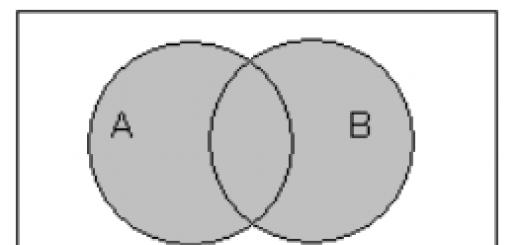
In addition to the conservation of momentum and energy in closed systems, one more physical quantity is conserved - the angular momentum. Consider first the vector product of the vectors and (Fig. 32).
A vector product of vectors is called such a vector, the modulus of which is equal to:
where is the angle between the vectors and .
The direction of the vector is determined by the gimlet rule if it is rotated from to along the shortest path.
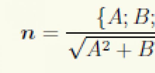
There is an expression for determining the cross product:
1. Moment of force about a point and about an axis.
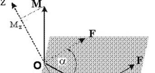
Let us first introduce the concept of moment of force. Let a certain force act on a particle whose position is determined using the radius vector relative to the origin of point 0 (Fig. 33).
Let's call the moment of force about the point 0 a vector quantity:
In this case, the vector of the moment of force is directed perpendicular to the plane of the figure towards us. It follows from the figure that the value of . Let's call it the shoulder of the moment of force. The shoulder of the moment of force is the distance from the reference point 0 to the line of action of the force.
The moment of force about some axis passing through point 0 is the projection of the vector of the moment of force about point 0 onto this axis.
2. Moment of a pair of forces. Properties of the moment of a pair of forces.
Consider two parallel, equal in magnitude, opposite in direction forces that do not act along one straight line (Fig. 34). Such forces are called a pair of forces. The distance between the straight lines along which these forces act is called the shoulder of the pair.
The following designations are introduced here:
Radius vector of the force application point,
The radius vector of the force application point relative to the force application point .
The total moment of this pair of forces is defined as:
Since the forces form a pair, then, therefore:
It can be seen that the moment of a pair of forces does not depend on the choice of the origin of the points of application of forces.
3.Moment of the particle's momentum relative to the axis and relative to the point.
Let us now turn to the concept of angular momentum. Let a particle of mass m, whose position is determined using the radius vector relative to the origin of point 0, move with speed (Fig. 35).
Let us introduce a vector , which we will call the angular momentum of the particle relative to the point 0. We will call the value the shoulder of the angular momentum relative to the point 0.
The angular momentum about the axis passing through the point 0 is the projection of the angular momentum about the point onto this axis.
1. Consider movement along a straight line. At a height h, an airplane of mass m flies horizontally with a speed V (Fig. 36).
Let's find the angular momentum of the aircraft relative to some point 0. The modulus of the angular momentum is equal to the product of the momentum and its arm. In this case, the momentum arm is equal to h. Hence:
2. Consider movement in a circle. A particle of mass m moves along a circle of radius R with a constant modulo velocity V (Fig.37). Find the angular momentum of the particle about the center of the circle 0.
The angular momentum of the particle M== рR=const.
4. Particle moment equation
By definition, the angular momentum of a particle relative to some point 0 is:
Let's find the time derivative of the right and left parts of this expression:
The first term vanishes according to the vector product rule. We finally have:
This expression is called the particle moment equation.
The rate of change of angular momentum is equal to the moment of forces.
5. Moment of momentum of the system of particles.
The law of change and conservation of the angular momentum of a system of particles.
Consider a system of particles interacting with each other, which is acted upon by external forces. We set the position in space of the particles of this system using radius vectors relative to some origin 0. Let us write the total angular momentum of this system relative to the point:
Find the change in the total moment:
Let's write this system of equations:
…………………………………..
We sum the left and right parts of this system and consider the pairwise sums in the first term on the right.
According to Newton's third law, all other pairwise sums will also vanish. Consequently, the total moment of all internal forces of interaction between particles is equal to zero. Then it remains:
The angular momentum of a system of particles changes the moment of external forces. For a closed system of particles, the law of conservation of angular momentum is satisfied.
6. Orbital and proper moment of momentum of the system of particles.
Let's consider a system of N particles whose position is set using radius vectors relative to some reference point 0 (Fig. 38).
Let the position of the center of mass C of this system be determined using the radius vector . Then the position of the i-th particle relative to the origin 0 is defined as:
Let us write the total angular momentum of the system of particles relative to the origin 0:
The first term is called the orbital angular momentum of the system:
The second term is called the intrinsic moment of the system:
Then the total angular momentum of the system relative to the reference point 0 has the form:
7. Movement in the central field of forces.
Consider a particle moving in a central force field. Recall that in such a field the force acting on a particle depends only on the distance between the particle and the origin. In addition, the force is always directed along the radius vector of the particle.
It is easy to understand that in this case the moment of the central force is equal to zero and, therefore, the law of conservation of the angular momentum relative to the origin is fulfilled.
Since , then the trajectory of the particle is always located in the plane in which the force vectors and the radius vector lie. In the central field, particles move along flat trajectories.
During the time dt, the radius vector of the particle will describe the area dS (Fig. 39).
This area is equal to half the area of the parallelogram built on the radius vector and the elementary displacement vector. As you know, the area of such a parallelogram is equal to the modulus of the cross product. Thus, we can now write:
Let's call the value - sectorial speed, and for it we get the expression:
Because in the central field M =const, then, consequently, the sectorial velocity remains constant.
Conclusion: when a particle moves in a central force field, its radius vector describes equal areas in equal time intervals.
This statement is Kepler's second law.
8. The problem of two bodies.
The problem of particle motion in a central force field has many applications. Consider the problem of the motion of two bodies. Consider two particles interacting only with each other. Let us find out how the center of mass of such a system behaves. From the theorem on the motion of the center of mass of a closed system, we can conclude that it either rests or moves in a straight line and uniformly.
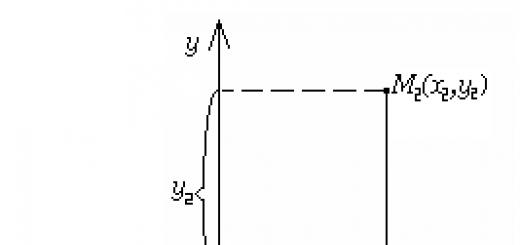
We will solve the problem of two bodies in the system of their center of mass. As is known, the radius vector of the center of mass of the system is determined using the expression:
From the law of conservation of momentum of such a closed system it follows that:
Let's introduce a radius vector that determines the position of the second particle relative to the first (Fig. 40):
Then it is possible to obtain expressions for the relationship of the radius vectors that determine the position of the particles relative to their common center of mass, with the radius vector of their relative position:
Let us now consider this problem from the energy point of view. Let us denote by and - the speeds of particles relative to their center of mass, and by - the speed of the second particle relative to the first. Then, from the law of conservation of momentum of a system of particles, the following expressions can be obtained:
Let us write the total mechanical energy of this system of particles:
Here U(r 21) is the system's own potential energy.
This expression can be transformed as follows:
where the following designation is introduced - the reduced mass.
We see from the point of view of energy, this system of particles behaves like a single particle with a reduced mass and moving at a relative speed. The problem of two bodies is reduced to the problem of the motion of one body.
If the dependence is known, then the main problem can also be solved, i.e. find dependencies and .
Let us write the equation of motion (Newton's second law) for each of the particles in the central field:
There is a minus sign on the right side of the second equation, because .
Dividing the first equation by m 1, and the second by m 2, we get:
Subtract the first equation from the second:
Then finally:
From here you can find the dependency.
9. Movement of artificial satellites. space speeds.
Consider the motion of an artificial satellite of the Earth near its surface. Since only one force acts on the satellite - the force of gravitational attraction to the Earth, then we can write the equation of its motion in a circle:
where m is the mass of the satellite, M is the mass of the Earth, Rz is the radius of the Earth.
From here you can get the speed of the satellite:
Substituting the appropriate values, we get the speed V 1 = 8 km/s.
This speed is called first space(the speed that must be reported to the body so that it becomes a satellite of the Earth near its surface).
We have considered the simplest case of a satellite moving in a circular orbit. However, as the theory shows, in the two-body problem, other trajectories of motion of one particle relative to another are also possible - ellipses, hyperbolas and parabolas. Elliptical orbits correspond to the negative value of the total mechanical energy of the system, hyperbolic orbits correspond to the positive value of the total mechanical energy, and parabolic orbits correspond to the value of the total mechanical energy equal to zero.
Let's find the so-called second space velocity. This is the speed that must be imparted to the body so that it becomes a satellite of the Sun, while the body must move along a parabolic trajectory.
Let us write down the total mechanical energy of the satellite-Earth system, considering the Earth to be motionless:
Equating the total mechanical energy to zero, we obtain the second cosmic velocity:
Substituting the appropriate values, we get V 2 = 11.2 km/s.
SOLID BODY MECHANICS
VIII. Rigid Body Kinematics
1.Absolutely solid. Plane motion of a rigid body and its decomposition into translational and rotational..
Until now, we have used a material point as a physical model, but not all problems can be solved in this approximation. Let us now turn to the so-called absolutely rigid bodies. An absolutely rigid body is a body in which the distance between the particles of which it consists does not change. In other words, it is absolutely not deformable body.
We will consider flat motion rigid body, in which during the movement any of its points remains in one of the parallel planes. In a plane motion, the trajectories of each point of a rigid body lie in the same plane, and the planes of all trajectories either coincide or are parallel.
Any complex motion of a rigid body can be represented as the sum of simpler motions: translational and rotational . Translational called such a movement of a rigid body in which a line connecting any two points of the body retains its direction in space. Translational motion is not necessarily linear, for example, a cabin in a ferris wheel (Fig. 41).
rotational called such a movement in which the trajectories of all points of a rigid body are concentric circles with a center lying on the axis of rotation. A cylinder rolling on a table performs both translational motion and rotational motion around its axis of symmetry.
Let us show how plane motion can be decomposed into translational and rotational (Fig. 42).
It can be seen from the figure that from position 1 to position 2 the body can be moved first to position translationally, and then to position 2 rotationally around the axis . Such a division into translational and rotational motion can be done in an infinite number of ways, but the rotation is always carried out through the same angle .
Thus, plane motion can be represented as translational with the same speed for all points of the body and rotational with the same angular speed. For linear velocities of points of a rigid body, this can be written as:
Here is the radius vector of any point of the rigid body.
For example, the rolling of a cylinder on a horizontal surface (Fig. 43) can be represented as a translational motion of all points with a speed V 0 and rotation around an axis coinciding with its axis of symmetry 0, with an angular velocity ., or as a translational motion with a speed and rotation with that the same angular velocity but around the axis.
The movement of a rigid body can be represented as a set of only rotations around the so-called instantaneous axis. This axis can be either within the rigid body itself, or it can be outside of it. The position of the instantaneous axis changes with time. In the case of a rolling cylinder, the instantaneous axis coincides with the line of contact between the cylinder and the plane.
Let's depict in fig. 44 the direction of the instantaneous velocities of some points of the cylinder relative to the fixed frame of reference. The speed of point A is equal to zero at each moment of time, because. it is the sum of the translational speed and the linear speed equal in absolute value. The speed of point C is twice the speed, and so on.
Let's see how the speed is oriented relative to the fixed frame of reference of any point of the cylinder. To do this, we write the condition of an absolutely rigid body for two arbitrary points in the following form:
Differentiate with respect to time the right and left sides:
We connect point A with the instantaneous axis of rotation, then and . Therefore, we have:
This condition implies the perpendicularity of the corresponding vectors, i.e. .
Particle angular momentum(material point) relative to the point O is called a vector quantity equal to:
L- axial vector. The direction of the angular momentum vector L is determined so that the rotation around the point O in the direction of the vector p around the axis passing through the point O obeys the right screw rule. The vector r, p and L form a right screw system. In the SI system, the angular momentum has a unit of measure: [L]=1 kg m 2 / s.
Consider two examples of calculating the angular momentum of a particle relative to the point O.
Example 1 . The particle moves along a rectilinear trajectory, particle mass-m, momentum-p. Find L and ½ L½ . Let's make a drawing.

from formula (22.4.) it follows that the modulus of angular momentum can only be changed by changing the modulus of speed, since when moving along a straight path, the shoulder l remains constant.
Example 2 . A particle of mass m moves along a circle of radius R with velocity V. Find L and ½ L½ . Let's make a drawing.

Fig.22.3. The direction of the momentum vector of a particle moving along a circle of radius R with a speed V.
|
(22 .5 ) |
|
(22 .6 ) |
The angular momentum is considered relative to the point C. From formula (22.6.) It follows that the modulus of the angular momentum can only change by changing the modulus of speed. Despite the continuous change in the direction of the vector p, the direction of the vector L remains constant.