1. Exclude from the kinematic scheme of the mechanism passive connections and extra degrees of freedom (W).
2. Replace flat kinematic pairs of class 4 with kinematic pairs of class 5, while the replacement mechanism must have the number of degrees of freedom of the previous mechanism and perform all its movements.
3. Start disconnecting the structural group from the most distant from the leading link of the mechanism.
4. First of all, disconnect the structural group of class II (if it is not possible to disconnect the structural group of class II, disconnect the structural group of class III, etc.).
5. Make sure that when the structural group is disconnected, the remaining mechanism retains its operability, i.e. didn't fall apart.
Replacement of a class 4 kinematic pair with a class 5 kinematic pair.
Any flat kinematic pair of the 4th class is replaced by two kinematic pairs of the 5th class (rotational and translational), interconnected by fictitious links.
Examples: Given a gear mechanism. It is required to replace class 4 kinematic pairs with class 5 kinematic pairs (Fig.):
Solution :
Here n=2, P 5 \u003d 2, P 4 \u003d 1 (t.B),
then W=3 2-2 2-1=1
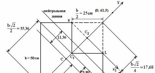
Through t. IN carry out a tangent t-t to link 2. Through t. IN at an angle to t-t carry out N-N. From points BUT And FROM draw perpendiculars to N-N. At their points of intersection with N-N install rotational kinematic pairs of class 5: TO And L K-L.
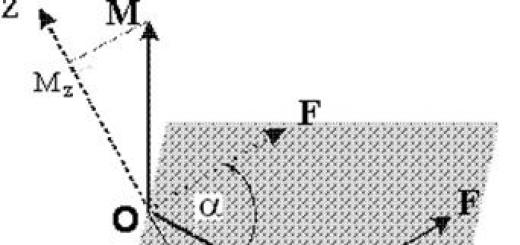
The angle of engagement of link 1 and link 2 with each other.


(W).
Here n=3, P 5 =4, P 4 =0, then W=3 3-2 4=1
Friction mechanism given, rice.

Here: n=2, P 5 \u003d 2, P 4 \u003d 1 (t.B)
Then: W=3 2-22-1=1
| Rice. eleven |


Make up a kinematic diagram of the replacement mechanism and determine the number of degrees of freedom W,
Here: n=3, P 5 =4, P 4 =0. Then W=3 3-2 4=1
Given cam mechanism, rice.
 Solution:
Here n=2, P5=2, P4=1
Then W=3 2-2 2-1=1
Through t. IN carry out a tangent t-t to
link 1 and link 2. Through t. IN perpendicular to t-t carry out N-N. On the N-N find the centers of curvature of link 1 and link 2, install rotational kinematic pairs of class 5 in them: TO And L, which connect fictitious links K-L, rice.


Make up a kinematic diagram of the replacement mechanism and determine the number of degrees of freedom W, rice.
Here n=3, P5=4, P4=0, then W=3 3-2 4=1
Examples of performing a structural analysis of the mechanism.
Given: Kinematic diagram of the mechanism.
It is required to perform a structural analysis of the mechanism.
 Solution:
a) Movable links: 1,2,3,4,5 . Kinematic pairs: A, A", B, C, D, E, E"
b) W=3n-2P 5 - P 4, here n=5, P5=7, P4=0 → W=3 5-2 7=1
Consider the remaining mechanism 0,1,2,4,0 The mechanism has fallen apart, because when link 1 rotates, link 4 will be stationary.
Therefore, it was done incorrectly.
In this case, the class III structural group is disconnected
Structural group III class 3 orders.
3. Links remain 0.1 with a kinematic pair BUT.
W=3 1-2 1=1
Therefore, the leading link is a class I mechanism.
Structure formula I (0,1) → III 3 (2,3,4,5).
The main mechanism of class III.
1) Disconnect links 1,2 with kinematic pairs A,B,C
n=2, P 5 =3, W=3·2-2·3=0.

 2) disconnect links 3,4
with kinematic pairs A, D, E,
2) disconnect links 3,4
with kinematic pairs A, D, E,
n=2, P 5 =3, W=3 2-2 3=0
Structural group II class 2 orders
3) links remain 0,5 with kinematic pair E",
 n=1, P 5 =1, W=3 1-2 1=1
The leading link is a class I mechanism.
The main mechanism of class II.The kinematic diagram of the mechanism of the 5th class is given. It is required to perform a structural analysis of the mechanism.

Links: 0, 1, 2, 3, 4, 5, 0, 6, 0
Kinematic pairs: A, B, C, D, D", E, F, K
W=3n-2P 5 -P 4, here n=6, P 5 =8, P 4 =0 → W=3 6-2 8=2

1) disconnect links 4,5 with kinematic pairs D,D,E.
n=2, P 5 =3, W=3·2-2·3=0.
| Rice. 41 |
The main mechanism with links is considered 0,1,2,3,6,0.
 The mechanism did not fall apart, because. when rotating the links 1 and 6 will be mobile.
Structural group detachment done correctly.
2) Disconnect from the main mechanism links 2 and 3 with kinematic pairs B,C,F, rice.

n=2, P 5 =3, W=3 2-2 3=0
Structural group II class 2 orders.
3) leading links remain 0,1 with kinematic pair BUT and links 0,6 with kinematic pair TO.


| Rice. 44 |
Class I mechanism Class I mechanism
4) write the formula for the structure of the mechanism:
II 2 (2.3) → II 2 (4.5)
I (0.6) Class II movement
Kinematic analysis of gear mechanisms.
The task of the kinematic analysis of gear mechanisms is to determine their gear ratios.
A gear mechanism is a mechanism consisting of gears and designed to transfer rotation from one shaft of the machine to its other shaft with a change in the magnitude of the transmitted torque (M cr).
The torque depends on the gear ratios, the larger the gear ratio, the greater the torque (M kr). The gear mechanism is installed between the engine and the working mechanism.
A gear mechanism that serves to reduce the speed or number of revolutions of the motor shaft is called a gearbox; to increase - multiplier; moreover, the gearbox increases the torque (M kr), and the multiplier reduces it.
There are simple, planetary (satellite), stepped, differential and closed differential gear mechanisms.
Planetary gear mechanisms, gear ratio.
Private gear ratios of planetary gear mechanisms.
A planetary gear mechanism is a mechanism in which at least one axis with a group of gear wheels (satellites) is movable in space.
Planetary mechanisms are used to obtain large gear ratios with smaller dimensions and weight, compared with simple gear mechanisms. The planetary gear mechanism consists of a central wheel, satellites (the number of satellites is from 2 to 12), a stationary wheel and a carrier (the central movable axis of the satellites). They have W=1 and are of the following types: 1) James reducer (Fig. 8)

Here: 1 - central (solar) wheel; 2 - satellite; 0 - fixed wheel; H- carrier (movable kinematic link).
W = 3n - 2P 5 - P 4
Here: n = 3 (1,2,H), P 5 = 3 (A, B, C), P 4 = 2 (D, E).
Then: W=3 3-2 3-2=1
The gear ratio of the planetary gear mechanism is determined by the Willis formula:
 (1)
(1)
Ordinary cylindrical planetary gear mechanism 1-0 (Fig. 9).

Then:  (2)
(2)
Substitute (2) into (1): 
We determine: a) reverse gear ratio

c) the gear ratio from the central gear to any movable wheel (for example, xatellite)
 .
.
2) David's gearbox with external gearing (Fig. 10).

Two or more gears rigidly fixed on one axle represent one wheel and are designated by the same numbers; moreover, the second, third gear will be with one, two, etc. strokes. In Fig. 10: 2 - 2 ".  , (1)
, (1)
where - gear ratio of the stepped planetary mechanism.

Then:  (2)
(2)
Substitute (2) into (1):  .
.
Send your good work in the knowledge base is simple. Use the form below
Students, graduate students, young scientists who use the knowledge base in their studies and work will be very grateful to you.
Hosted at http://www.allbest.ru/
Analysis of gear mechanisms.Open involute gearing.Calculation of parametersopen involute gear
Initial data
Radial clearance coefficient, = 0.25.
Tooth head height factor, = 1.
Gear module, m = 10.
Number of teeth, .
We accept bias coefficients: .
Teeth profile angle, b = 20°.
Determine the engagement angle:
according to the table we determine:
Determine the dividing center distance:
Determine the center distance:
We determine the coefficient of perceived displacement:
Determine the equalization bias factor:
The calculation of the geometric parameters of gear 1 and wheel 2 is given in the table:
Table - Calculation of the geometric parameters of the involute transmission
|
Defined value. |
Calculation formula |
Values |
||
|
Gear_1 |
Wheel_2_ |
|||
|
Tooth pedicle height |
||||
|
Tooth head height |
||||
|
Pitch circle radius |
||||
|
Basic circle radius |
||||
|
Pitch Circle Radius |
||||
|
Tooth tip circle radius |
||||
|
Profile angle |
||||
|
The radius of the circle of depressions |
||||
|
Tooth thickness along the pitch circle |
||||
|
District step |
||||
|
Tooth thickness along the main circumference |
||||
|
The thickness of the tooth along the circumference of the vertices |
Determine the gear overlap ratio:
Construction of an involute link
1 We put the position of the axes of rotation and draw the center line.
2 We draw the arcs of the initial circles (and and mark the pole of the engagement P at the point of their contact.
3 We build the remaining circles of the gears: the tops of the teeth (radii and), dividing (radii and), basic (radii and), tooth cavities (radii and). At the same time, we check the accuracy of the graphical construction by the size of the radial clearance.
4 Draw a common tangent to the main circles. At the same time, it must necessarily pass through the engagement pole P. Since this tangent is an engagement line, characteristic points are marked on it: and - points of contact with the main circles and and - points of intersection of the engagement line with the circles of the tops of the teeth.
The segment of the engagement line enclosed between the points and is the theoretical engagement line, and the segment enclosed between the points and is the working section of the engagement line.
We show the angle of engagement. To do this, we draw a straight line through the gearing pole P perpendicular to the center distance line. The angle of deviation of the engagement line from this line is the engagement angle.
5 We build the involutes of the gears that are in contact at the gearing pole Р. To build the tooth profile of the first wheel, the segment of the theoretical gearing line P is divided into three equal parts. These segments (taking them equal to the lengths of the arcs) are set aside along the main circle to the right and left of the point and mark the points. Through these points we draw tangents to the main circle and set aside unit segments on them, the number of which corresponds to the number of the point from which the tangent is drawn. For more accurate drawing of tangents, we first draw straight lines connecting these points with the axis of rotation, and restore perpendiculars to these straight lines. The smooth curve drawn through the obtained points is the involute profile of the right side of the first wheel.
6 To build the opposite side of the tooth, it is necessary to draw its axis of symmetry. We determine its position by setting aside half the thickness of the tooth along the dividing circle. Setting aside the value /2 along the dividing circle, we get a point. The straight line connecting this point with the axis of rotation will be the axis of symmetry of the tooth. By measuring the chords of these arcs with a compass and making notches on the corresponding circles, we obtain points belonging to the involute of the opposite side of the tooth.
Determine the fillet radius:
The involutes of the second wheel are constructed in a similar way.
We determine graphically the coefficient of overlap of the gear train:
gear
The error in determining the overlap coefficient graphically is:
Hosted on Allbest.ru
...Similar Documents
Classification of gears according to the shape of the tooth profile, their type, the relative position of the shaft axes. The main elements of the gear wheel. Calculation of the main geometric parameters of a spur gear. Measuring the diameter of the tops of the teeth of the wheel.
presentation, added 05/20/2015
Motor selection: the procedure for calculating the required power and other parameters. Rationale for the choice of gear: selection of materials, calculation of allowable stress and bending, dimensions of wheel and gear teeth, verification calculation of gearbox shafts.
term paper, added 01/11/2013
Kinematic calculation and determination of gear ratios of the drive. Mechanical parameters on the drive shafts. Definition of V-belt and spur gear. Calculation of pulley diameters. Determination of the center distance and belt wrap angle.
term paper, added 12/18/2011
Calculation and geometric design of gear transmission parameters, determination of tolerances of spur gears, choice of interface type. Calculation of landings and executive dimensions of plug gauges for gearing and for rolling bearings.
test, added 09/08/2010
Scheme design, structural and kinematic study of the lever mechanism, force calculation. Calculation of geometric parameters of non-equidisplaced involute gear transmission of external gearing from the condition of no undercutting. Flywheel calculation.
term paper, added 03/24/2010
Calculation of a gear transmission for resistance to contact and bending fatigue. Refinement of the load factor. Determination of the actual circumferential speed, hole diameters in the gear and wheel hubs, tooth inclination angle, allowable bending stresses.
test, added 04/22/2015
Designing an involute gear. Transfer calculation algorithm. Checking the given offset factors. Finding the engagement angle. Equalizing displacement coefficients for a rack-and-pinion circuit are a positive value. Dividing circles.
abstract, added 03/06/2009
Calculation and rationing of gear accuracy. The choice of degrees of gear accuracy. The choice of the type of pairing, the teeth of the transmission wheels. The choice of indicators for monitoring the gear. Calculation and rationing of the accuracy of smoothly cylindrical joints.
test, added 08/28/2010
Determination of drive life. Calculation of power and engine speed. Selection of materials for gears, verification of allowable stresses. Calculation of the geometric parameters of a closed spur gear, shafts and bearings.
term paper, added 11/18/2012
Types of planetary gears and their design. The gear ratio of the planetary gear and the determination of the number of its teeth. Construction of the planetary mechanism. Types of gears. Qualitative indicators of engagement. Construction of three teeth of the 1st and 2nd wheels.
General concepts and definitions. A planetary gear mechanism is called, which, in addition to the central wheels rotating on fixed axles, has at least one link with movable axles. Gears are planted on the latter, meshing with the central wheels and rolling around them. Thus, the peculiarity of the planetary mechanism is the presence of one or more movable axes that make circular motions around a fixed central axis.
Wheels sitting on movable axles are called satellites and are indicated by letters g or /, and a link that carries satellites on its axes is called carrier and is denoted by the letter Y.
A simple planetary mechanism is one in which one of the central wheels is motionless (stopped). Examples of simple planetary mechanisms are shown in fig. 11.18. When the carrier rotates, the movement of the satellites resembles the movement of the planets. Rotating around its axes, fixing
Rice. 11.18.
but - with external gearing of the sun wheel with satellite; b - with internal gearing of the crown wheel with satellite.
mounted on the carrier, they, together with the carrier, rotate around the main fixed axis.
Since the axes of the central wheels and the carrier lie on the same straight line, any planetary mechanism is coaxial. The stopped central gear with external gearing is called solar, and the stopped central gear with internal gearing (see Fig. 11.18, b) is often referred to as the crown.
The scheme of a single-stage planetary mechanism consists of four moving links: a central wheel but with number of teeth zv satellite g with the number of teeth z 2, carrier H and center wheel b internal engagement with the number of teeth z 3 . The degree of mobility of this mechanism, calculated by the formula of P. L. Chebyshev
It is known that the complete certainty of the movement of the driven links of the mechanism is possible only in the case when the number of leading links coincides with the number of degrees of freedom. Therefore, the mechanism under consideration, which has two degrees of freedom, must have two leading links.
A planetary mechanism with two or more degrees of freedom is called differential. Such a mechanism allows summing up on the driven link the movements received from two or more independent driving links.
The differential mechanism can be turned into a simple planetary or closed planetary by stopping (fixing) one of the central wheels or by imposing an additional kinematic connection on the mechanism, as a result of which the degree of mobility of the mechanism becomes equal to one.
So, if in the mechanism under consideration (Fig. 11.19, b) fix the center wheel b, then we get a simple planetary mechanism with one degree of mobility. Here, the leading and driven links can be aw H or me and but.
On fig. 11.20 shows two diagrams of a closed planetary mechanism - one-stage and two-stage. The method of closing them in this case is the same. It consists in the fact that the central wheel b rigidly fastened to gear c, and gear is fixed on the carrier axis I d. Gears from And d engaged with gears z 5 and z (. or z (. and z 7 ), which rotate on separately remote and fixed axes 0 56 or O fi7 .

Rice. 11.19.
but - all moving links are free - differential mechanism; b - fixed central crown wheel - planetary mechanism

Rice. 11.20.
The whole variety of planetary gears, both flat and spatial (bevel), can be reduced to several basic types, classifying them either by type of engagement (BUT - external, / - internal), or according to the number of main links. Cylindrical one- and two-stage gears, classified as 2K-# and ZK gears, have received the greatest use in industry.
In 2K-Ya gears (Fig. 11.21), the main links are two central wheels but And b and carrier I (hence the designation 2K-I). On fig. 11.21 shows the possible options for two-stage gears, in which the central wheels are engaged with a two-crown satellite d And /. They can also be classified according to the types of gearing as //-transmissions,.//-transmissions and LL-transmissions. On the basis of 2K-I gears, almost all closed planetary gears used in mechanical engineering are formed.
In ZK gears (Fig. 11.22), the main links are three wheels a > b And e> and the carrier I serves only to install the axes of the satellites and does not bear the load from external moments.

Rice. 11.21.
but - //-broadcast; b- LL transmission; in-//-broadcast

Rice. 11.22.
but - stopped wheel b; b- stopped wheel e
For example, consider the manipulator shown in Fig. five.
The links of the mechanism are denoted by Arabic numerals, their number is n = 5.
Kinematic pairs included in this mechanism:
p 5 = 3, including two rotational (A, B) and one translational (C);
p 4 \u003d 2, a spherical hinge with a pin (D) and a cylindrical pair (B). As long as the grip (link 5) is not connected to the object of manipulation, the kinematic chain is open.
Determine the degree of mobility:
W = 6 5 - 54 - 42 = 7
Thus, the mechanism has 7 independent movements for orientation and movement in the workspace.
After the grip is brought to the object of manipulation and combined with it, the number of moving links becomes one less, i.e. n = 4. The number of kinematic pairs remains unchanged. Now you can determine the maneuverability of the manipulator.
Rice. 5. Structural diagram of the manipulator arm
W = 65 - 53 - 42 = 1
The fact that the maneuverability is equal to one means that with a fixed position of the grip (fixed point B), the links of the mechanism can change their position depending on the position of one of the links: for example, when link 2 rotates, the lengths of the sides VD and DE will simultaneously change, as well as angles of the VDE triangle, that is, the position of links 3 and 4 is a function of the angle of rotation of link 2.
Task 3. Theme "Kinematic analysis of gear mechanisms"
The task of the kinematic analysis of gear mechanisms is to determine the gear ratio and rotational speed of the output links.
The simplest gear train consists of two wheels with teeth, through which they interlock with each other. According to the shape of the wheels, cylindrical, bevel, elliptical, figured gears are distinguished.
The most common gear wheels are round, i.e. cylindrical and bevel. A bevel gear rotates between shafts whose geometric axes intersect. According to the shape and arrangement of the teeth on the wheel, straight, oblique, chevron, circular and other curved teeth are distinguished.
The constancy of the gear ratio of the gear train is ensured by the shape of the tooth profile. The most widely used involute profile, as it is easy to manufacture (by copying or running).
When cutting gears with the number of teeth of an involute profile less than a certain limit value, the roots of the teeth are undercut, as a result of which the strength of the teeth is significantly reduced. To eliminate undercutting, gears with offset or so-called corrected gears are used.
The main geometric parameters characterizing the gearing include: module, gearing angle, diameters of the pitch, initial and main circles, overlap ratio.
Gear mechanisms are divided into mechanisms with fixed and movable axes of rotation.
To perform a kinematic analysis, it is necessary to determine the gear ratio of the gear train.
gear ratio U 1 i is the ratio of the angular velocity ω 1 of the gear 1 to the angular velocity i th ω i gear wheel. Instead of angular velocities, you can also use the concept of rotational speed n:
U 1 i= ω 1 / ω i= n 1 / n i . (3.1)
The angular velocities of the wheels in engagement are inversely proportional to the radii of the pitch circles r w and the number of gear teeth Z.
Thus, the gear ratio for a pair of cylindrical external gear wheels (Fig. 6, a)

 internal gearing (Fig. 6, b)

The total gear ratio of a multi-link mechanism is equal to the product of the gear ratios of the individual stages
U 1 i = U 12 U 23 U 34 ...U (i -1) i (3.3)
determine the number of steps in the transmission;
find the gear ratio of each stage;
multiply the gear ratios of the steps.
The resulting number will be the gear ratio of the multistage transmission.
Mechanisms with one degree of freedom, having a fixed wheel, are called planetary. A feature of planetary mechanisms is the presence of gear wheels (satellites) with moving geometric axes.

b 
Continuation of Fig.6.
Mechanisms with the number of degrees of freedom W > 2, which usually do not have a fixed wheel, are called differential.
Since satellites in gears with moving axles perform a complex rotational movement, the determination of the gear movement is carried out using the inverted movement method.
Condition. The initial data for task 3 are given in Table 4, the kinematic schemes of gear mechanisms are shown in Fig. 7. Determine the number of degrees of freedom of the mechanism, the unknown number of teeth of the wheels and the frequency of rotation of the wheels.

Scheme 0 Scheme 1
Scheme 2 Scheme3

Diagram 4 Diagram 5
Diagram 6 Diagram 7
Continuation of fig. 7


Diagram 8 Diagram 9
End of Fig. 7
Table 4
Variants of initial data for task 3
|
Value |
The penultimate digit of the passbook cipher |
|||||||||
|
Z 4 | ||||||||||
|
Define | ||||||||||
Lab #24
Kinematic analysis of gear mechanisms
Objective:development of skills in drawing up kinematic diagrams of gear mechanisms and determining their gear ratios.
1. Determination of the gear ratio analytically
1.1. 3gear mechanisms with fixed axles
gear ratiois called the ratio of the angular velocity link " k"to the angular velocity link "":
(cm. ; ; ).
For a flat mechanism consisting of two gears and a rack, we have:
![]()
where n– rpm, speed;
z – number of teeth;
is the radius of the starting circle.
The conditionally set "minus" sign shows that the engaged wheels rotate in different directions with external touch (Fig. 1, but), and the plus sign shows that the wheels rotate in the same direction with internal contact (Fig. 1.1, b).

a) b)
Fig.1
The implementation in single-stage transmissions of large gear ratios (approximately >8) becomes impractical, since the diameter of one of the wheels is very large. Attwo-stage gears are used, with >40 - three-stage.
The gear ratio of a multi-stage transmission is equal to the product of the private gear ratios of individual stages (simple mechanisms).
For the stepped mechanism shown in Fig. 2, the gear ratio is determined by the formula:

Fig.2
Due to the parallelism of the shafts I and V to the found gear ratio, as in the case of a single-stage transmission, we attribute a sign. It is determined by the rule of arrows. In our case, the valuemust be assigned a minus sign.
Example 1 A four-stage transmission is set (Fig. 3), representing the drive from the electric motor to the machine. Wheel tooth numbers: z 1 = 18, z 2 = 27, z 3 = 12, z 4 = 24, z 5 = 19, z 6 = 57.

Fig.3
Determine the rotational speed of the driven wheelVif the motor shaft speed= 1440 rpm.
Gear ratio:
![]() rpm
rpm
Example 2

Fig.4
Wheels 1 and 3 rotate in opposite directions ("rule of arrows").
1.2. Planetary and differential gears
In all the gear mechanisms discussed above, the gear shafts rotated in fixed bearings, i.e. the axles of all wheels did not change their position in space. There are multi-stage gears, the axes of individual wheels of which are movable. Such gear mechanisms with one degree of freedom (W= 1) called planetary mechanisms, and with the number of degrees of freedom two or more () – differential.
The analytical method for studying the kinematics of such mechanisms is based on the method of motion reversal (see ; ; ). All links of the mechanism are given an additional angular velocity, which is equal in magnitude, but opposite in direction of the carrier's angular velocity. As a result, the carrier turns out to be motionless, and the differential (planetary) mechanism turns into a gear train with fixed wheel axes (inverted mechanism).
Example 3 Determine the number of revolutions of the carrier () and satellite ( ), as well as the direction of their rotation, if the drive shaft (wheel 1) rotates with a frequency= 60 rpm. Number of teethz 1 = z 3 = 20, z 2 = 40.

Fig.1.5
Modules of all wheels are the same. The wheels are made without displacement of the original contour. Wheel 4 is stationary. Wheel 3 rolls over wheel 4.
Number of degrees of freedom of the mechanism:
where n – number of moving links;
is the number of kinematic pairs of the fifth class,
is the number of kinematic pairs of the fourth class.
The considered mechanism is planetary.
Unknown number of teeth (z 4 ) we determine from the coaxiality condition:
where are the radii of the starting circles,i= 1,…4.
Since the wheels are made without shifting the original contour, the initial circles coincide with the dividing ones:
![]()
Since, according to the condition, the modules of all wheels are the same, then:
To determine the gear ratio, we apply the motion reversal method. Let the moving links in the mechanism under consideration rotate with angular velocities. It is obvious that the relative motion of the links will not change if the whole mechanism is given additional rotation around the central axis with a frequency of rotation -n n (that is, with a frequency equal in magnitude, but opposite in direction, to the rotation of the planet carrier). Then the speeds will change accordingly and take the values:
|
Link |
Actual speed |
Rotation frequency after the message to the mechanism of additional rotation |
|
Wheel 1 |
n 1 |
|
|
Wheel 4 |
n 4 |
|
|
carrier n |
n n |
|
Thus, when informing the whole mechanism of reversed motion with a frequency -n n the carrier will be motionless, and the planetary mechanism will turn into an ordinary gear (with fixed axes). Gear ratio of the latter:
![]()
or, passing to the angular velocities ():
![]()
Here are the actual angular velocities, andare the angular velocities in reversed motion, i.e. angular velocities of an ordinary gear mechanism derived from a planetary one.
For an ordinary gear mechanism:
![]()
![]()
![]()
because actually n 4 = 0.
The plus sign indicates that input link 1 and carrier rotate in the same direction:
![]()
To determine the speed of the satellite:
![]()
![]()
n 2 = -210 rpm.
The minus sign shows that the pinion assembly 2 and 3 and the planet carrier rotate in opposite directions.
2. Work order
In this work, it is necessary to perform a kinematic analysis of three gear mechanisms, including one planetary or differential. For each gear mechanism, a kinematic diagram is drawn up and the gear ratio is determined first in a general form, and then its value is calculated.
The kinematic diagram must be drawn up correctly in compliance with the conventions adopted in the preparation of kinematic diagrams (GOST 2.703-74, GOST 2.770-68).
After submitting a report on the work, each student must solve a control problem.
protocol form
"KINEMATIC ANALYSIS OF GEAR MECHANISMS"
Student Group Supervisor
1. Movement number _____
Kinematic scheme
The overall gear ratio of the mechanism:
a) calculated value;
b) obtained experimentally.
2. Movement number _____
Kinematic scheme, etc.
I've done the work Accepted the job
Control tasks
The task is assigned by the teacher.
The missing number of gear teeth is determined from the condition of coaxiality, assuming that all the gears of the mechanism have the same module and engagement angle.
Task #1Define n6
|
var. no. |
z1 |
z2 |
z3 |
z4 |
z5 |
n 1 |

Task #2Define n 5
|
var. no. |
z1 |
z2 |
z3 |
z4 |
z5 |
n 1 |
|
1053 |

Task #3Define n n
|
var. no. |
z1 |
z2 |
z 2" |
z3 |
z 3" |
z4 |
n 1 |

Task #4Define n n
|
var. no. |
z1 |
z2 |
z 2" |
z3 |
z4" |
z5 |
n 1 = n 5 |

Task number 5Define n6
|
var. no. |
z1 |
z2 |
z 2" |
z 3" |