Statement of the work reciprocity theorem (Betty's theorem), proved in 1872 by E. Betti: the possible work of the forces of the first state on the corresponding displacements caused by the forces of the second state is equal to the possible work of the forces of the second state on the corresponding displacements caused by the forces of the first state.
24. Theorem on the reciprocity of displacements (Maxwell)
|
|
|

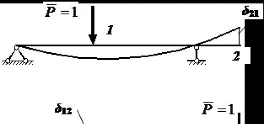
Let and. Theorem on the reciprocity of displacements taking into account the accepted designation of displacement from a unit force, it has the form: The theorem on the reciprocity of displacements was proved by Maxwell. Statement of the reciprocity theorem: the displacement of the point of application of the first unit force, caused by the action of the second force, is equal to the displacement of the point of application of the second unit force, caused by the action of the first unit force
25. Rayleigh's theorem on the reciprocity of reactions. 

26. Gvozdev's theorem on the reciprocity of displacements and reactions.


27. Determination of displacements from the load. Mohr formula.

Mora formula


28. Determination of displacements from temperature effects and from displacement.
Temperature effect.


Draft


29. Vereshchagin's rule. Trapezoid multiplication formula, Simpson's formula.


Trapezoidal formula.
![]()
Multiplication formula for curvilinear trapezoids
31. Properties of statically indeterminate systems.
To determine the forces and reactions, the equations of statics are not enough, it is necessary to involve the equations of the continuity of deformation and displacement.
Efforts and reactions depend on the ratio of the stiffness of the individual elements.
Changes in temperature and settlement of the support cause the appearance of internal forces.
In the absence of load, a state of self-stress is possible.
32. Determination of the degree of static indeterminacy, the principles of choosing the main system of the method of forces.
For statically indeterminate systems W<0
The number of extra connections is determined by the formula:
L = -W+ 3K,
where W is the number of independent geometric parameters that determine the position of the structure on the plane without taking into account the deformation of the structure (the number of degrees of freedom), K is the number of closed contours (contours in which there is no hinge).
W\u003d 3D - 2Sh - Co
Chebyshev's formula for determining the degree of freedom, where D is the number of disks, W is the number of hinges, Co is the number of support rods.
OSMS should be geometrically invariable.
Must be statically determinable (remove L extra connections).
This system should be easy to calculate.
If the original system was symmetrical, then the OSMS is chosen as symmetrical if possible.
33. Canonical equations of the force method, their physical meaning.
Canonical equations:

Physical meaning:
The total movement in the direction of each remote link should be = 0
34. Calculation of the coefficients of canonical equations, their physical meaning, verification of the correctness of the found coefficients.

Moving in the direction of this remote connection caused by the jita unit force.

Movement in the direction of this remote connection caused by an external load.


In order to check the correctness of the found coefficients, you need to substitute them into the system of canonical equations and find X1 and X2.

Consider two states of an elastic system in equilibrium. In each of these states, a certain static load acts on the system (Fig. 4a). Let's denote the displacements in the directions of forces F1 and F2 through, where the index "i" shows the direction of displacement, and the index "j" - the cause that caused it.
Let us denote the work of the load of the first state (force F1) on the displacements of the first state through A11, and the work of the force F2 on the displacements caused by it - A22:
Using (1.9), works A11 and A22 can be expressed in terms of internal force factors:

Let us consider the case of static loading of the same system (Fig. 5a) in the following sequence. First, a statically increasing force F1 is applied to the system (Fig. 23b); when the process of its static growth is over, the deformation of the system and the internal forces acting in it become the same as in the first state (Fig. 23a). The work of the force F1 will be:
Then a statically growing force F2 begins to act on the system (Fig. 5b). As a result, the system receives additional deformations and additional internal forces arise in it, the same as in the second state (Fig. 5a). In the process of increasing the force F2 from zero to its final value, the force F1, remaining unchanged, moves down by the amount of additional deflection and, therefore, performs additional work:
The force F2 does the work:
The total work A under sequential loading of the system by forces F1, F2 is equal to:
On the other hand, in accordance with (1.4), the total work can be defined as:
Equating expressions (1.11) and (1.12) to each other, we obtain:
A12=A21 (1.14)
Equality (1.14) is called the reciprocity of work theorem, or Betti's theorem: the work of the forces of the first state on displacements in their directions, caused by the forces of the second state, is equal to the work of the forces of the second state on displacements in their directions, caused by the forces of the first state. Omitting intermediate calculations, we express the work of A12 in terms of bending moments, longitudinal and transverse forces arising in the first and second states:
Each integrand on the right side of this equality can be considered as the product of the internal force arising in the section of the rod from the forces of the first state and the deformation of the element dz caused by the forces of the second state.
Proof of the work reciprocity theorem
Let's mark two points 1 and 2 on the beam (Fig. 15.4, a).
We apply statically at point 1 the force . It will cause a deflection at this point, and at point 2 -.
We use two indices to designate displacements. The first index means the place of movement, and the second - the reason causing this movement. That is, almost like on a letter envelope, where we indicate: where and from whom.
So, for example, means the deflection of the beam at point 2 from the load.
After the growth of strength is completed. we apply at point 2 to the deformed state of the beam the static force (15.4, b). The beam will receive additional deflections: at point 1 and at point 2.
Let's make an expression for the work that these forces do on their respective displacements: .
Here the first and third terms are the elastic work of forces and . According to Clapeyron's theorem, they have a coefficient . The second term does not have this coefficient, since the force does not change its value and does the possible work on the displacement caused by another force.
The beginning of possible displacements, being a general principle of mechanics, is of great importance for the theory of elastic systems. As applied to them, this principle can be formulated as follows: if the system is in equilibrium under the action of an applied load, then the sum of the work of external and internal forces on possible infinitesimal displacements of the system is equal to zero.
Where  - external forces;
  - possible movements of these forces;
  - the work of internal forces.
Note that in the process of making a possible displacement by the system, the magnitude and direction of external and internal forces remain unchanged. Therefore, when calculating work, one should take half, and the full value of the product of the corresponding forces and displacements.
Consider two states of a system in equilibrium (Fig. 2.2.9). Able  the system is deformed by the generalized force
  (Fig. 2.2.9, a), in the state
  - force
  (Fig. 2.2.9, b).

The work of the forces of the state  on state transitions
  , as well as the work of state forces
  on state transitions
  , will be possible.
 (2.2.14)
Let us now calculate the possible work of the internal forces of the state  on displacements caused by state load
  . To do this, consider an arbitrary element of the rod with length
  in both cases. For flat bending, the action of the remote parts on the element is expressed by the system of forces
  ,
, ,
, (Fig. 2.2.10, a). Internal forces have directions opposite to external ones (shown by dashed lines). On fig. 2.2.10, b shows external forces
  ,
, ,
, acting on the element
  able
able  . Let us determine the deformations caused by these forces.
Obviously elongation of the element  caused by forces
 .
.
Work of internal axial forces  on this possible move
 . (2.2.15)
Mutual angle of rotation of element faces caused by pairs  ,
,
 .
.
Work of internal bending moments  on this move
 . (2.2.16)
Similarly, we determine the work of transverse forces  on movements caused by forces
 . (2.2.17)
Summing up the work obtained, we obtain the possible work of the internal forces applied to the element  rod, on displacements caused by another, completely arbitrary load, marked with the index
Summing up the elementary work within the rod, we obtain the total value of the possible work of internal forces:
 (2.2.19)
Let us apply the beginning of possible displacements, summing up the work of internal and external forces on the possible displacements of the system, and obtain a general expression for the beginning of possible displacements for a flat elastic rod system:
 (2.2.20)
That is, if the elastic system is in equilibrium, then the work of external and internal forces is in the state  on possible displacements caused by another, completely arbitrary load, marked with the index
  , equals zero.
Theorems on the reciprocity of work and displacement
Let us write down the expressions for the beginning of possible displacements for the beam shown in Fig. 2.2.9 by accepting for the state  as possible displacements caused by the state
  , and for the state
  - movements caused by the state
  .
.
 (2.2.21)
 (2.2.22)
Since the expressions for the work of internal forces are the same, it is obvious that
 (2.2.23)
The resulting expression is called the work reciprocity theorem (the Betti theorem). It is formulated as follows: the possible work of external (or internal) forces of the state  on state transitions
  is equal to the possible work of external (or internal) forces of the state
  on state transitions
  .
.
Let us apply the work reciprocity theorem to a special case of loading, when in both states of the system one single generalized force is applied  And
And  .
.

Rice. 2.2.11
Based on the work reciprocity theorem, we obtain the equality
 , (2.2.24)
which is called the theorem on the reciprocity of displacements (Maxwell's theorem). It is formulated as follows: the movement of the point of application of the first force in its direction, caused by the action of the second unit force, is equal to the movement of the point of application of the second force in its direction, caused by the action of the first unit force.
Theorems on the reciprocity of work and displacements greatly simplify the solution of many problems in determining displacements.
Using the work reciprocity theorem, we determine the deflection  beams in the middle of the span under the action on the moment support
  (Fig. 2.2.12, a).
We use the second state of the beam - the action at point 2 of the concentrated force  . Angle of rotation of the reference section
  we determine from the condition of fixing the beam at point B:


Rice. 2.2.12

According to the reciprocity work theorem
 ,
,
Work reciprocity theorem. Theorem on the reciprocity of displacements
Consider a linearly deformable system in two different states corresponding to two different loads (Fig. 5.15). For simplicity of calculations, let us consider a simple two-support beam sequentially loaded by two concentrated forces.
Figure 15. Direct and reverse order of load application
Equating the total work for the direct and reverse order of application of loads, we obtain
The work actually done by a force on displacements caused by another force or forces is called additional work.
According to the reciprocity of work theorem, the work of the forces of the first state to move the second state is equal to the work of the forces of the second state to move the first state.
Similarly, the reciprocity of the additional work of internal forces can also be proved.
Figure 16. Reciprocity of additional work of internal forces.
Using the law of conservation of energy, it can be shown that the additional work of external forces is equal in absolute value to the additional work of internal forces:
Taking
we obtain a theorem on the reciprocity of displacements.
The displacement of the point of application of a unit force in its direction, caused by the second unit force, is equal to the displacement of the point of application of the second unit force in the direction of the latter, caused by the action of the first unit force.
Determination of displacements by Mohr's method
Instead of the system of forces F 1 and F 2 , we introduce the cargo and auxiliary states:
Figure 17. Introduction of cargo and auxiliary states
Let us write the work reciprocity theorem for these two states:
After summing over individual sections of the beam, we obtain the Mohr integral
Example 5.2. Consider an example of using the Mohr integral to determine displacements for a cantilever beam loaded with a concentrated force
Figure 18. Building a load and auxiliary diagram for a cantilever beam
We use the Mohr integral.
In practice, this approach is difficult to use. This difficulty is overcome by the organization of integration, the integration is easily implemented on a computer.
Graph-analytical method for determining displacement during bending. Vereshchagin's method
We introduce two simplifying circumstances:
Linear function within the considered section.
Figure 19 Graph-analytical calculation of the Mohr integral
The last integral is the static moment of the figure ABCD about the y-axis. Work
represents the ordinate taken on the auxiliary diagram under the center of gravity of the cargo.
where n is the section number.
Example 5.3. Consider the cantilever beam again
Figure 20. Using the Vereshchagin method for a cantilever beam
More difficult cases:
1. Multiplying a trapezoid by a trapezoid
Rice. 21. Multiply a trapezoid by a trapezoid
To multiply a trapezoid by a trapezoid, you can proceed to multiplying a rectangle by a trapezoid and a triangle by a trapezoid.
The definition of multiplying a rectangle by a trapezoid means that we take A f along the rectangle, and M k c along the trapezoid.
The permutation rule only works on linear diagrams.
2. Parabolic segment
Figure 22. Area and position of the center of gravity for a parabolic segment
3. Concave parabolic triangle
Figure 23. Area and position of the center of gravity for a concave parabolic triangle
4. Convex triangle
Figure 24. Area and position of the center of gravity for a convex parabolic triangle
5. Convex parabolic trapezoid.
Figure 25. Partitioning of areas and position of centers of gravity for a convex parabolic trapezoid
Example: 5.4. Let us consider a more complex case of loading a cantilever beam, when all three types of external loads act. It is necessary to determine the maximum angle of rotation of the beam
Rice. Cantilever beam with simultaneous action of three loads
I way. Let's replace the diagram M f with a set of simpler figures.
that is, the vertex of the parabola is outside the beam.
To build an auxiliary diagram, you must:
1. Consider a beam without external loads.
2. At a given point, apply F=1 or M=1, respectively, to determine the deflection or angle of rotation. The direction of action of external loads is arbitrary.
3. Considering the unit load as external, we determine the reactions and build diagrams.
The formula for determining the angle of rotation by the Vereshchagin method will take the following form
where - the ordinate taken on the auxiliary diagram M to under the center of gravity of the cargo diagram - taking into account the division of the cargo diagram into elementary figures
When constructing a curved beam axis, we use:
1. The sign of the generalized displacement. For the considered case, the point is rotated clockwise.
2. Use the sign of the bending moment on the load diagram.
An approximate view of the bent axis of the beam is shown in fig. 5.24.
II way. Using the principle of superpositions.
Rice Using the principle of superposition